Difference between revisions of "WorkUnit:Disrupted Cities - road network"
Frankiezafe (Talk | contribs) |
Frankiezafe (Talk | contribs) (/* half-edgesThe half-edge data structure is called that because instead of storing the edges of the mesh, we store half-edges. As the name implies, a half-edge is a half of an edge and is constructed by splitting an edge down its length. We'll call th...) |
||
| Line 120: | Line 120: | ||
[[File:DC scan 0009.jpeg|150px]] | [[File:DC scan 0009.jpeg|150px]] | ||
| − | === half-edges<ref name="half-edges">The half-edge data structure is called that because instead of storing the edges of the mesh, we store half-edges. As the name implies, a half-edge is a half of an edge and is constructed by splitting an edge down its length. We'll call the two half-edges that make up an edge a pair. Half-edges are directed and the two edges of a pair have opposite directions. Source: [http://www.flipcode.com/archives/The_Half-Edge_Data_Structure.shtml | + | === half-edges<ref name="half-edges">[[File:2.-Directed-Graph.png|400px]] - [[File:Article halfedge.png|400px]] - The half-edge data structure is called that because instead of storing the edges of the mesh, we store half-edges. As the name implies, a half-edge is a half of an edge and is constructed by splitting an edge down its length. We'll call the two half-edges that make up an edge a pair. Half-edges are directed and the two edges of a pair have opposite directions. Source: [http://www.flipcode.com/archives/The_Half-Edge_Data_Structure.shtml flipcode.com]. '''Doubly connected edge list''', also known as half-edge data structure. Source:[[wikipedia:Doubly_connected_edge_list|wikipedia]]</ref> === |
See '''method''' chapter for a resume of the implementation. | See '''method''' chapter for a resume of the implementation. | ||
Revision as of 13:26, 12 April 2017
This page describes the different steps implemented in the city generator package to detect block in the road's network, in a fast and clean way.
Contents
block detection
right vector


Finding the closest road on the right at a crossroad[1].
To generate the bocks of building based on the roads structure, the method I’m building is based on a simple idea: when you arrives at a crossroad, you take the first street on the right and you go on like this until you reach a dead-end or your starting point. If you reach your starting point, the succession of roads you took defines a block of building. In theory. This technique has been suggested by Michel Cleempoel, on the way back from school.
After a bit of preparation of the road network (removing orphan roads, having no connection with others, and dead-ends parts of the roads), the real problem arouse: how do you define right in a 3d environment, without an absolute ground reference. Indeed, I can configure the generator to use the Y axis (top axis in ogre3d) in addition to X & Z.
At a crossroad, you may have several possibilities of roads. In the research, these possible roads are reduced to 3d vectors, all starting at world’s origin. The goal is to find the closest vector on the right of the current one, called the main 3d vector in the graphic above..
The right is a complex idea, because it induces an idea of rotation. The closest on the right doesn’t mean the most perpendicular road on the right side. Let say I have 4 roads to choose from. Two going nearly in the opposite direction of the road i’m on, one perpendicular and one going straight on.
If I compute the angles these roads have with the current one, results are:
- 5°,
- -5°,
- 90°,
- and 170°.
The winner is not the 90°, but the 5° road! If I sort them, the last one must be the -5°, who is the first on the left.
3d plane from a 3d vector
The first thing to do is to define reference plane. To do so, you get the normal vector of the road by doing a cross product with the UP axis (Y axis in this case). The normal gives you a second vector, perpendicular to the road, and therefore defines a plane. Let’s call it VT plane, for Vector-Normal plane. For calculation, we need the vector perpendicular to this plane, rendered by crossing the road and its normal, let’s call it the tangent vector. Until here, it’s basic 3d geometry.
projection of 3d vectors on a plane
We can now project all the possible roads on the VT plane. These are the yellow vectors in the graphic. The math are clearly explained by tmpearce[2]. Implemented in processing, it gives:
float d = othervector.dot( tangent );
vec3f projectedvector;
projectedvector += tangent;
projectedvector *= d * -1;
projectedvector += othervector;
We are nearly done!
angle between 3d vectors
The projected vectors will help the angle calculation. Indeed, the current vector and the projected ones being coplanar, they share the same normal. The way to get the angle between 2 coplanar vectors is described by Dr. Martin von Gagern[3], once again. See Plane embedded in 3D paragraph for the code i’ve used.
And… tadaaammmm! The number rendered by the method is the angle i was searching for, displayed in degrees in the graphic above.
The c++ implementation of the methjod is looking like this:
RDListIter it;
RDListIter ite;

vec3f dir = ( *from )-( *this );
vec3f normal = GLOBAL_UP_AXIS.getCrossed( dir );
normal.normalize( );
vec3f tangent = dir.getCrossed( normal );
tangent.normalize( );

it = connected_dots.begin( );
ite = connected_dots.end( );

RoadDot* sel_dot = 0;
float smallest_angle = -1;

for (; it != ite; ++it ) {

    if ( (*it) == from ) {
         continue;
    }

    vec3f nv = ( *( *it ) )-( *this );
    nv.normalize( );

    // http://stackoverflow.com/questions/9605556/how-to-project-a-3d-point-to-a-3d-plane#9605695
    float d = nv.dot( tangent );
    vec3f nn = nv + tangent * d * -1;

    // http://stackoverflow.com/questions/14066933/direct-way-of-computing-clockwise-angle-between-2-vectors
    float dot = nn.x * dir.x + nn.y * dir.y + nn.z * dir.z;
    float det =
              nn.x * dir.y * tangent.z +
              dir.x * tangent.y * nn.z +
              tangent.x * nn.y * dir.z -
              nn.z * dir.y * tangent.x -
              dir.z * tangent.y * nn.x -
              tangent.z * nn.y * dir.x;

    float angle = atan2( det, dot );

    if ( angle < 0 ) {
         angle += TWO_PI;
    }

    if ( sel_dot == 0 || smallest_angle > angle ) {
         sel_dot = ( *it );
         smallest_angle = angle;
    }

}

return sel_dot;
- RDListIter is a typedef vector<RoadDot*>
- GLOBAL_UP_AXIS allows to define wich is the UP axis of the world.
- vec3f is a standard class for 3d vector manipulation, depending on your framework.
sketches


half-edges[4]
See method chapter for a resume of the implementation.
Isle::collect_oriented_segments(Road* r)
cases to foresee:
0. starting the road, previous dot has one connection
1. starting the road, previous dot has >1 connections > crossroad
2. along the road, current dot has two connections
3. along the road, current dot has >2 connections > crossroad
4. end of the road, current dot has one connection
5. end of the road, current dot has >1 connections > crossroad

A       B       C
o ----> o ----> o
        ^
        |
        |
        D

[f]  [f]  [b]  [b]  [f]
AB > BC > CB > BA > AB

[f]  [b]  [f]  [f]  [b]  [b]  [f]
AB > BD > DB > BC > CB > BA > AB


A       B       C
o ----> o ----> o
        |
        |
        v
        D

[f]  [f]  [b]  [f]  [b]  [b]  [f]
AB > BD > DB > BC > CB > BA > AB

cases [2,5] can happens simultaneously
It seems nearly impossible to create the relation between half-edges correctly in one pass: some half-edges tries to connect to not yet created half-edges. If the half-edges are generated on the fly, it will imply a check at each half-edge (HE) generation, to validate if the HE is already created or not.
A better approach seems to be: generation of all of them + creation of structures for crossroads, holding a pointer to the RoadDot and the list of all HEs connected to it. Connections can be resolved locally in a second pass. Let's try it.
Not yet functional: blocks are crossing roads...


The issue was coming from a method that sort the connections of a roaddot: RoadDot::rightSort(RDList& sorted). In its first implementation, I was just looping over the connections and storing in a list the result of the method RoadDot::getRight(RoadDot* from);, without checking in any way the angles between these dots. The block crossing street issue was caused by this inconsistency. I now use a skip list and I always use the first connection as a reference. Code is simple:
void RoadDot::rightSort( RDList& sorted ) {

   RDListIter it = connected_dots.begin( );
   RDListIter ite = connected_dots.end( );

   sorted.push_back( connected_dots[0] );
   RDList skip;
   skip.push_back( connected_dots[0] );

   for(; it != ite; ++it ) {
       RoadDot* d = getRight( connected_dots[0] , skip );
       if ( !d ) break;
       skip.push_back( d );
       if ( find( sorted.begin(), sorted.end(), d ) != sorted.end() ) {
           cout << "Double push in sorted!!!" << endl;
       }
       sorted.push_back( d );
   }

}
Each time a dot on the right is retrieved, it is added to the skip list for the next search. Sorting, in a word...
Algorithm can be very painful... but when they are logically correct, they work marvellously! The generation time of each map is nearly unchanged, and results are perfect: no holes!


Last screenshot shows the block rendered as plain shapes. The big yellow one is the outer bound of the map! With a method to measure surfaces of a random polygon, I'll be able to have the precise city area.
method
The first implementation of block detection was using the road's segment. The algorithm was starting with the 2 first dots of the first road and was travelling across the network by performing a getRight() at each dot having more than 2 connections.
A --- B ---- C ---- E
             |
             |
             D
A: {B}
B: {B,C}
C: {B,D,E}
E: {C}
The main issue of this method was that some blocks were not detected! Each time I was passing by through a dot, I was storing wich connections I used. In some cases, the dot needed to be used one time more than its number of connection.
A much better way to perform the search for blocks is based on the half-edges[4] technique. Indeed, each block uses a serie of half-edges, and these half-edges are used only by it. This approach is similar to directed graphs[5].
Any point of the map is a RoadDot, looking like this:
class RoadDot {
public:
   float x;
   float y;
   float z;
   vector<RoadDot*> connected;
I now using a specialised class for half-edges:
class OrientedSegment {
public:
   RoadDot* from;
   RoadDot* to;
   OrientedSegment* next;
and a class knowing wich half-edges are connected to wich dot:
class CrossRoad {
public:
   vector<OrientedSegment*> arriving; // ending at the key 'roaddot'
   vector<OrientedSegment*> leaving; // starting the key 'roaddot'
The crossroads are stored in a map< RoadDot*, CrossRoad >.
Getting all the half-edges at a given dot is now really easy: you pick the crossroad by looping on dots, and I get 2 lists of half-edges connected to the dot.
The OrientedSegment are generated during roads generation. Once the road's network is built, I run a method to connect all half-edges to each other.
The method is looking like this:
RoadDot* d = (*it); // 'it' is an iterator looping over all roaddots of the network
CrossRoad& cr = crossroads[d]; // the crossroad list, of type map< RoadDot*, CrossRoad >

if ( d->connected.size( ) == 1 ) {

   cr.arriving[ 0 ]->next = cr.leaving[0];

} else if ( d->connected.size( ) == 2 ) {

   cr.arriving[ 0 ]->next = cr.leaving[1];
   cr.arriving[ 1 ]->next = cr.leaving[0];

} else {

   vector<RoadDot*> sorted_dots;
   d->rightSort( sorted_dots );
   RDListIter first = sorted_dots.begin( );
   RDListIter next = sorted_dots.begin( );
   ++next;
   RDListIter it = sorted_dots.begin( );
   RDListIter last = sorted_dots.end( );

   OrientedSegment* os_arriving = 0;
   OrientedSegment* os_leaving = 0;

   for (; it != last; ++it, ++next ) {

       if ( next == last ) {
           next = first;
       }

      os_arriving = cr.getArriving( ( *it ) );
      os_leaving = cr.getLeaving( ( *next ) );
      os_arriving->next = os_leaving;

   }
}
After this, all half-edges are connected on each other correctly. Detecting blocks is a ultra-simple:
OrientedSegment* start = os;

Block* b = new Block( );

while ( os->next != start ) {

   b->add( os->from );
   os->blocked = true;
   os = os->next;

}
surfaces

The implementation of the method has been rather quick, even if the results have to be better checked, via a comparaison with a bounding box for instance. The color mapping in the screenshots below is as follow:
- surface ∈ [0,3000]: ( bigger => violet & more grey )
- hue: [0,3000] → [0,255]
- saturation [0,3000] → [255,180]
- huge surface (>=3000): white stroke
Image are 1920x1080, click on them to see details.


Legend:
- image #1: block's color depends on surface, roads are displayed as white lines
- image #2: block's color depends on surface, roads are not displayed
- image #3: block outline, a small cross indicates the center of each block
References
- ↑ Finding the closest road on the right at a crossroad, originally posted in polymorph.cool
- ↑ tmpearce on stackoverflow
- ↑ Dr. Martin von Gagern on stackoverflow
- ↑ 4.0 4.1
 -
- 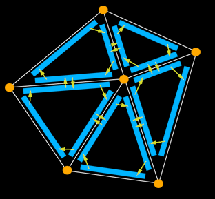 - The half-edge data structure is called that because instead of storing the edges of the mesh, we store half-edges. As the name implies, a half-edge is a half of an edge and is constructed by splitting an edge down its length. We'll call the two half-edges that make up an edge a pair. Half-edges are directed and the two edges of a pair have opposite directions. Source: flipcode.com. Doubly connected edge list, also known as half-edge data structure. Source:wikipedia
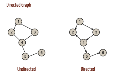
- ↑ In mathematics, and more specifically in graph theory, a directed graph (or digraph) is a graph that is a set of vertices connected by edges, where the edges have a direction associated with them. Source:Directed graph


Resources
- Doubly connected edge list, also known as half-edge data structure - wikipedia