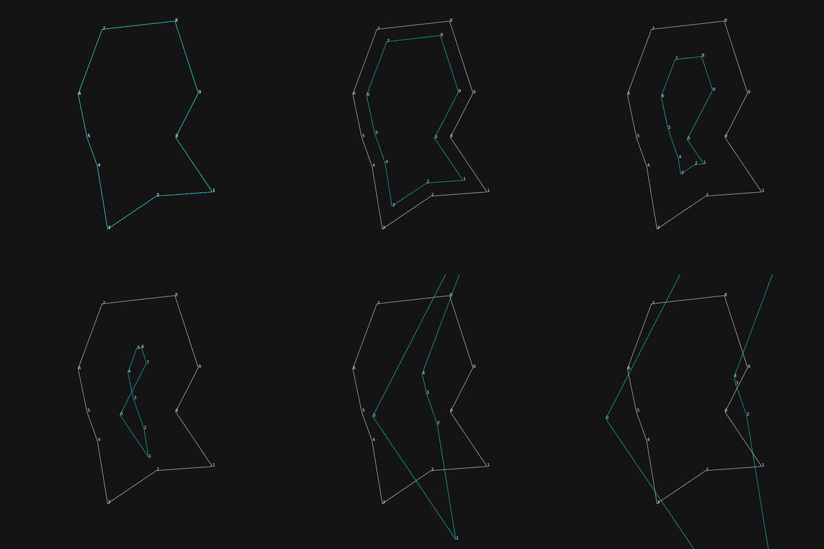
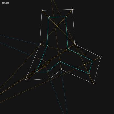
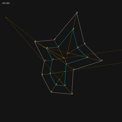
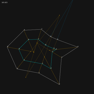
Difference between revisions of "WorkUnit:Disrupted Cities - road network"
Frankiezafe (Talk | contribs) (→Split events) |
Frankiezafe (Talk | contribs) (→related) |
||
| (62 intermediate revisions by the same user not shown) | |||
| Line 1: | Line 1: | ||
This page describes the different steps implemented in the city generator ''package'' to detect block in the road's network, in a fast and clean way. | This page describes the different steps implemented in the city generator ''package'' to detect block in the road's network, in a fast and clean way. | ||
| + | |||
| + | === repo(s) === | ||
| + | |||
| + | * [https://bitbucket.org/polymorphteam/shrink-demo Openframeworks demo of the lib] | ||
=== sketches === | === sketches === | ||
| Line 363: | Line 367: | ||
This approach was not keeping the segment's orientation. The shape was distorted. | This approach was not keeping the segment's orientation. The shape was distorted. | ||
| − | === Straight Skeletons === | + | === Straight Skeletons<ref name="straight skeleton">Straight Skeleton on [[wikipedia::Straight_skeleton|wikipedia]]</ref> === |
The method of Peter Palfrader called Computing Straight Skeletons by Means of Kinetic Triangulations<ref name="palfrader">Computing Straight Skeletons by Means of Kinetic Triangulations, Peter Palfrader master’s thesis, Department of Computer Sciences, University of Salzburg, 2013 - [[media:Palfrader - Computing Straight Skeletons by Means of Kinetic Triangulations, 2013 -Palfrader13-.pdf|pdf]]</ref> is proposing a way to solve this y using wavefront propagation. | The method of Peter Palfrader called Computing Straight Skeletons by Means of Kinetic Triangulations<ref name="palfrader">Computing Straight Skeletons by Means of Kinetic Triangulations, Peter Palfrader master’s thesis, Department of Computer Sciences, University of Salzburg, 2013 - [[media:Palfrader - Computing Straight Skeletons by Means of Kinetic Triangulations, 2013 -Palfrader13-.pdf|pdf]]</ref> is proposing a way to solve this y using wavefront propagation. | ||
| Line 668: | Line 672: | ||
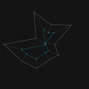
[[File:Straightskeleton 2017426105122.png|400px]] | [[File:Straightskeleton 2017426105122.png|400px]] | ||
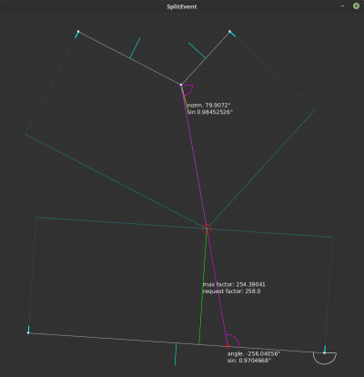
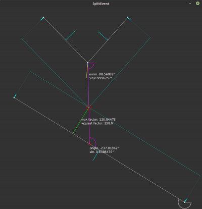
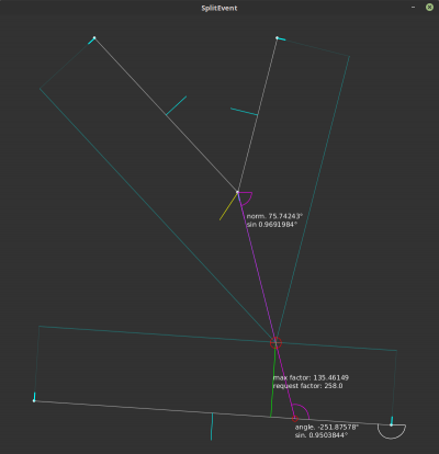
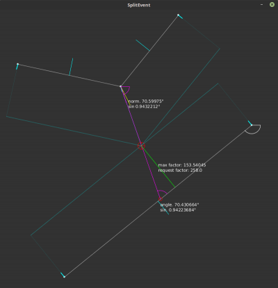
| − | With a little help from my friend<ref>Joe Cocker, With A Little Help Of My Friends, 1969, https://en.wikipedia.org/wiki/With_a_Little_Help_from_My_Friends</ref>, the calculaton is finally ''perfect''. Indeed, the angle between the bisector and the segment | + | With a little help from my friend<ref>Joe Cocker, With A Little Help Of My Friends, 1969, https://en.wikipedia.org/wiki/With_a_Little_Help_from_My_Friends</ref>, the calculaton is finally ''perfect''. Indeed, the angle between the bisector and the segment influences the division of the distance between the concave point and the intersection. |
If the segment is perpendicular to the segment, the form: | If the segment is perpendicular to the segment, the form: | ||
| − | + | File:Split-event-anticipation01.png | |
distance / ( 1 + sin( PI + concave_angle ) ) | distance / ( 1 + sin( PI + concave_angle ) ) | ||
is correct. But as soon the bisector has a slight angle, the allowed shrink factor has to be reduced by the sinus of the angle between the bisector and the segment. | is correct. But as soon the bisector has a slight angle, the allowed shrink factor has to be reduced by the sinus of the angle between the bisector and the segment. | ||
| − | I had to rebuild a simple processing<ref>Processing is a flexible software sketchbook and a language for learning how to code within the context of the visual arts. - https://processing.org/</ref> sketch to | + | I had to rebuild a simple processing<ref>Processing is a flexible software sketchbook and a language for learning how to code within the context of the visual arts. - https://processing.org/</ref> sketch to fix this. |
The core of the process lies in these lines: | The core of the process lies in these lines: | ||
| Line 698: | Line 702: | ||
[[File:SplitEvent 782.png|400px]] | [[File:SplitEvent 782.png|400px]] | ||
[[File:SplitEvent 784.png|400px]] | [[File:SplitEvent 784.png|400px]] | ||
| + | |||
| + | ==== selection ==== | ||
| + | |||
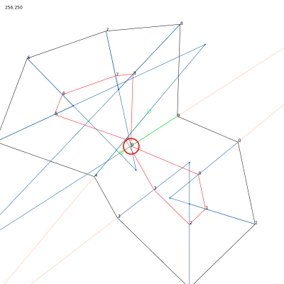
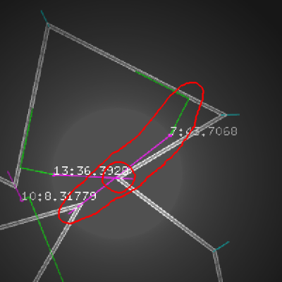
| + | The selection of the first split event for a specific point is much more tricky than expected. | ||
| + | |||
| + | In the case below, the bisector of the sharp angle do not cross the closest segment. The selection process remove the segment from the candidates. Result is dramatic: during shrink, this segment will cross the bisector! Anticipation is not correctly processed. | ||
| + | |||
| + | [[File:Split mess roadmap 2017052000061123068.png|533px]] [[File:Split mess roadmap detail.png|400px]] | ||
| + | |||
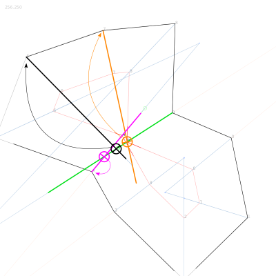
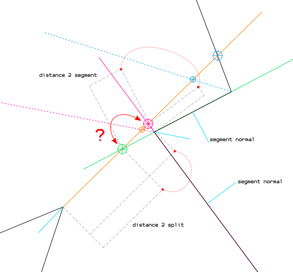
| + | The graph below shows a way to fix this. Let's call the point with the orange bisector the ''current'' point. | ||
| + | |||
| + | Split event selection process for the ''current'' point, step by step: | ||
| + | |||
| + | # segment normal dot ''current'' bisector is less than 0 > segment is out, the segment is oriented towards the ''current'' point, implying that another segment leading this one will cross the bisector closer > '''green intersection''' is removed; | ||
| + | # if intersection point between segment and ''current'' bisector is in segment > already solved by current code > '''blue intersection''' is processed; | ||
| + | # if intersection point between segment and ''current'' bisector is '''not''' in segment ('''pink intersection'''), do one of the bisectors of segment points cross the segment formed by ''current'' point and intersection point? | ||
| + | #* if yes > the segment, dragged by its point, will certainly cross the bisector at one point during shrink! > '''orange intersection''' is valid > '''pink intersection''' is processed; | ||
| + | #* if no > continue; | ||
| + | # last test concern the distance evaluation: the closest intersection must be kept, but in the case of outside crossing, the intersection has to be moved much closer from the ''current'' point, and the factor to apply depends on the angle of the bisector crossing the [''current'', intersection] segment. | ||
| + | |||
| + | [[File:Split-event-anticipation01.png]] | ||
| + | |||
| + | Better selection of split event is implemented. The problem case here above is solved. Algorithm has changed a bit. | ||
| + | |||
| + | Operations: | ||
| + | |||
| + | # if normal of the segment is not in the same direction has the ''current'' bisector, skipping segment | ||
| + | # retrieval intersection between bisector and line passing by the 2 points | ||
| + | # if intersection is not in the same direction as the ''current'' bisector, skipping segment | ||
| + | # calculation of intersection position, same as before | ||
| + | # if intersection happens outside of the segment and none of the normals of segment points cross the ''current'' bisector, skipping segment | ||
| + | # if there is already a split event detected for the ''current'' point and the shrink factor is higher than the previous event, skipping segment | ||
| + | # storage of the event if all conditions are ok | ||
| + | # once done, if an edge event exists for the ''current'' point, deletion of the split event | ||
| + | |||
| + | Note that tests 1, 3 & 5 are inverted for outer events. | ||
| + | |||
| + | [[File:Roadmap 2017052617321721259.png|400px]] [[File:Roadmap 2017052617322024527.png|400px]] | ||
| + | |||
| + | '''Limitations''' | ||
| + | |||
| + | There are still logical mistakes at step 5 of the algorithm. The exact test is this one: | ||
| + | |||
| + | bool pi_inter = false; | ||
| + | pi_inter = ( | ||
| + | (pu.concav && pi.shrink_multiplier > pu.shrink_multiplier) || | ||
| + | (!pu.concav && pi.shrink_multiplier < pu.shrink_multiplier) | ||
| + | ); | ||
| + | if (pi_inter) { | ||
| + | pi_inter = Geometry<T>::intersection( | ||
| + | pi, pi_and_normal, | ||
| + | pu, ii.result, | ||
| + | ii.result, | ||
| + | false, true); | ||
| + | } | ||
| + | |||
| + | Lines 3 & 4 test the ''shrink_multiplier'' of ''pu'' (''current'' point) and ''pi'', one of the segment's point. The ''shrink_multiplier'' is eqivalent to the speed of point, it is used to multiply the factor passed to the ''Multigon::shrink()'' method. The ''concav'' parameter is used to know if the event happens when shrinking or inflating the polygon. The idea was to only test the crossing of the normal and the bisector if the segment point is going 'faster' than the ''current'' point. This leads to errors in split event selection, shown here below. | ||
| + | |||
| + | [[File:Roadmap 20170526172203127011.png|400px]] [[File:Roadmap 20170526172210133377.png|400px]] | ||
| + | |||
| + | The problem is clear: the test forces the selection of the point having the biggest ''shrink_multiplier'', without taking into account other facts, such has the distance of the intersection, etc. | ||
| + | |||
| + | [[File:Splitevents sketches 5iUJVxtj.jpg|300px]] [[File:Splitevents sketches UvyfJ2ai.jpg-large.jpeg|300px]] | ||
| + | |||
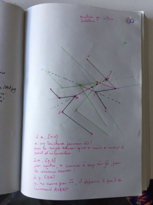
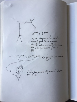
| + | After a bit of brain juice spread on paper, the resolution of the problem became obvious. If the split event happens outside of the segment, the split event is kept if the ''current'' point is the last to reach the intersection between bisectors. It's a basic math problem...<ref>The train problem is a basic math exercice, in wich distance and speed of the trains are involved - [http://www.mathscore.com/math/practice/Train%20Problems/ mathscore.com], [http://mathforum.org/dr.math/faq/faq.two.trains.html mathforum.org]</ref> | ||
| + | |||
| + | [[File:Roadmap 20170526172240163694.png|400px]] | ||
| + | |||
| + | Inner split events are now ok, but there is still some issues on the external selection. This shapes does not behave nicely on outer split. On the right side, cyan polygon, in the first case, and on the left (green polygon) in the second. The split event is triggered from the wrong point. | ||
| + | |||
| + | [[File:Roadmap 20170528191605504780.png||400px]] [[File:Roadmap 20170528191609508865.png||400px]] | ||
| + | |||
| + | Solved in 2 minutes: error was due to a stupid inverted test on distance for outer splits... | ||
| + | |||
| + | [[File:Roadmap 2017052819303639379.png|400px]] | ||
| + | |||
| + | ==== Simplier version (p5.js) ==== | ||
| + | |||
| + | One of the big problem in split event detection is when the bisector of the point is not crossing the segment (see [[#selection|selection of segment]] for details). | ||
| + | |||
| + | The first implemented method was based on detection of bisectors' intersection. The method is unsafe. A better method is to create a temporary polygon representing the surface covered by the segment when shrunk, and verify that the event point is belonging to the surface. | ||
| + | |||
| + | It has been implemented in this sketch (): | ||
| + | |||
| + | <html><iframe src="files/split_event/index.html" width="600" height="600" scrolling="no" frameBorder="0"></iframe></html> | ||
| + | |||
| + | manipulation: | ||
| + | |||
| + | * right-click & drag points to move them | ||
| + | * right-click & drag anywhere else to modify offset | ||
| + | |||
| + | === C++ === | ||
| + | |||
| + | It was time to leave Java and re-implement the methods in C++. I'm working in openfremworks to prepare the library. The classes processing the polygons are 100% independent from OF's one, even the vector3 class. Details of the code will be done once the lib will be finished. | ||
| + | |||
| + | The important idea is to use a **Multigon** object, able to manage several polygon. It will be very useful when split events will occur. It also allows to cut into smaller polygon a self-intersecting polygon. | ||
| + | |||
| + | For the moment: | ||
| + | |||
| + | * multiple edge events are managed correctly & | ||
| + | * polygon grows or shrink smoothly. | ||
| + | |||
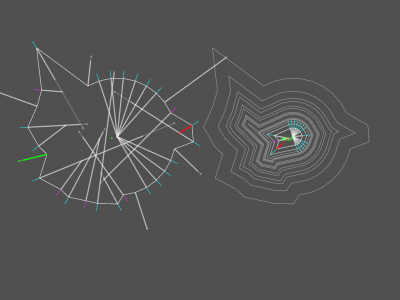
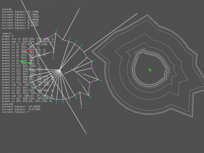
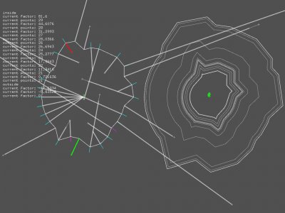
| + | [[File:Roadmap 2017050618124659274.png|400px]] [[File:Roadmap 2017050619513552380.png|400px]] [[File:Roadmap 20170506200912152992.png|400px]] | ||
| + | |||
| + | <html> | ||
| + | <iframe src="https://player.vimeo.com/video/218176416?title=0&portrait=0&byline=0" width="640" height="480" frameborder="0" webkitallowfullscreen mozallowfullscreen allowfullscreen></iframe> | ||
| + | </html> | ||
| + | |||
| + | In the current vetrsion, several improvements have been done: | ||
| + | |||
| + | * new event '''collapse''', indicates when a shape is too small to be shrinked; | ||
| + | * when a shape collapse, the position of its center is kept along the shrink steps; | ||
| + | * concurrent events (collapse, edge & split) are managed correctly in different subparts of the general shape; | ||
| + | * and the whole is not crashing anymore (!). | ||
| + | |||
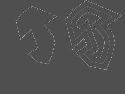
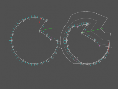
| + | There are still errors in split events calculations, as shown in the video. Once done, the next worksite will focus on shapes with sharp spikes, when the angle between 2 segments is equal to 360°. | ||
| + | |||
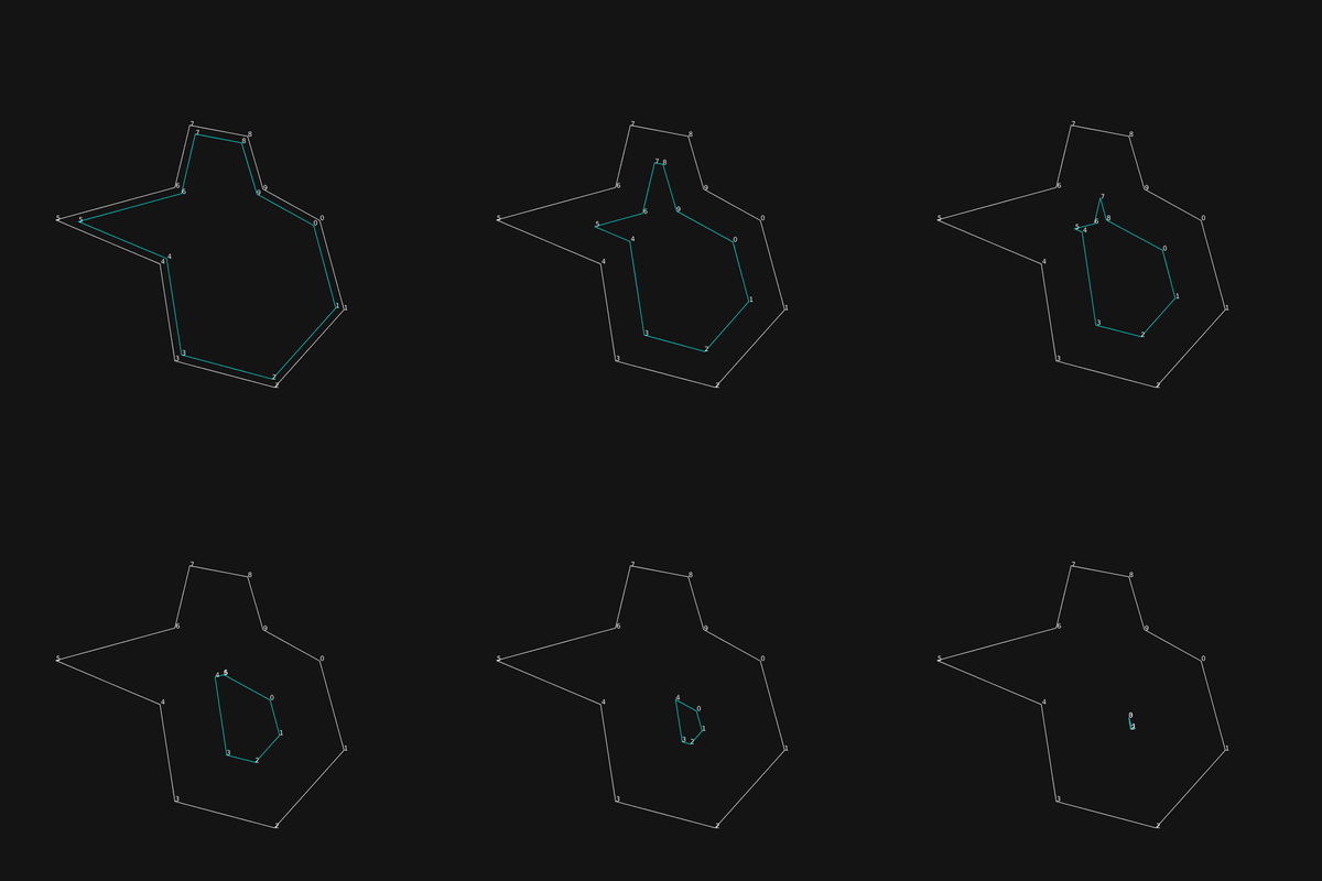
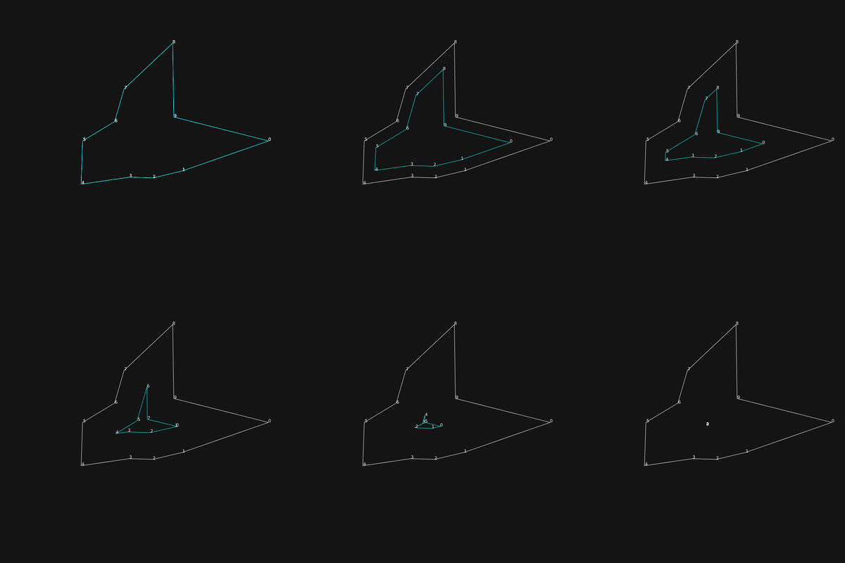
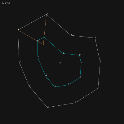
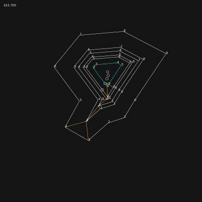
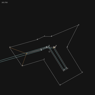
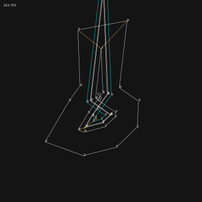
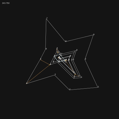
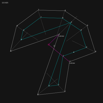
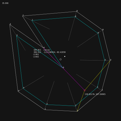
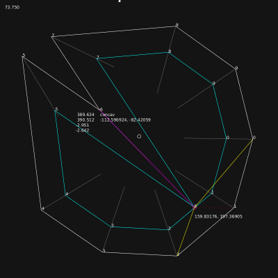
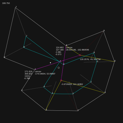
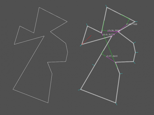
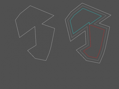
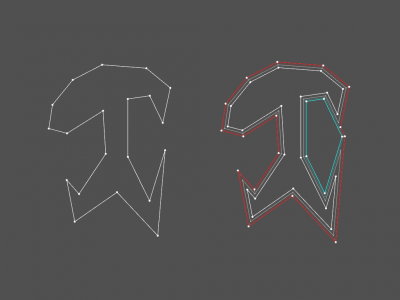
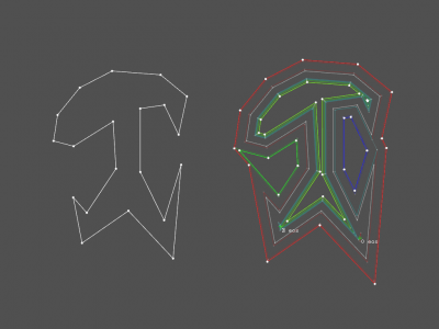
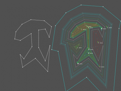
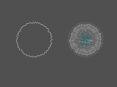
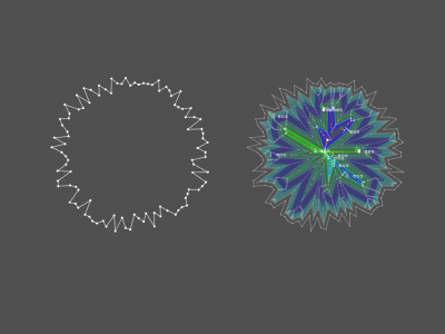
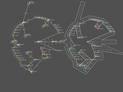
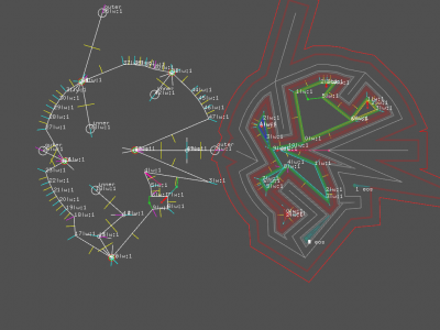
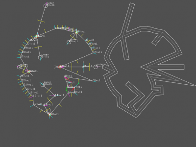
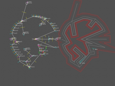
| + | After refining [[WorkUnit:Disrupted_Cities_-_road_network#selection|split event selection]] process, shrink can be performed on complex shapes. Screenshots below are random generated shapes with 100 points. | ||
| + | |||
| + | [[File:Roadmap 2017052818375921653.png|400px]] [[File:Roadmap 2017052818385533561.png|400px]] | ||
| + | |||
| + | '''video''' | ||
| + | |||
| + | <html> | ||
| + | <iframe src="https://player.vimeo.com/video/219729750?title=0&portrait=0&byline=0" width="800" height="600" frameborder="0" webkitallowfullscreen mozallowfullscreen allowfullscreen></iframe> | ||
| + | </html> | ||
| + | |||
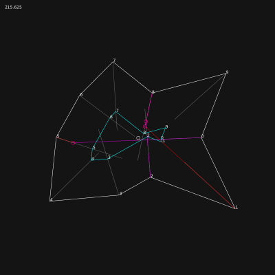
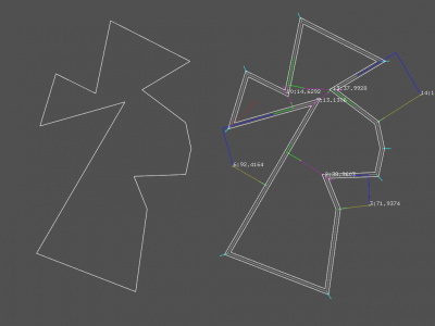
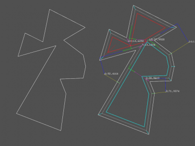
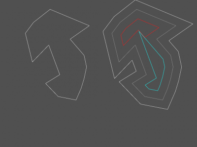
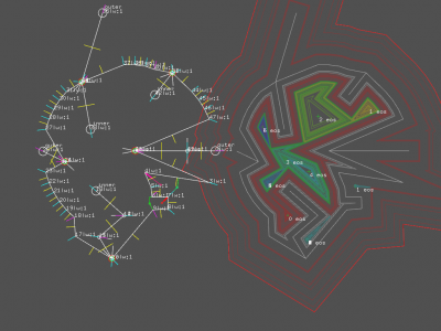
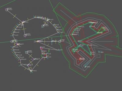
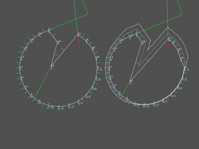
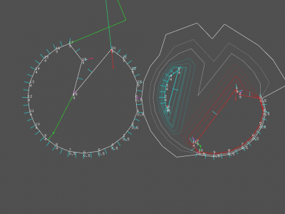
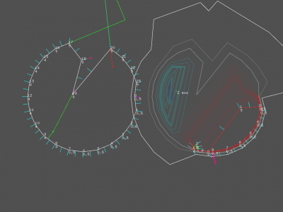
| + | Visual syntax: | ||
| + | |||
| + | * left polygon is the original shape to shrink; | ||
| + | * result of the process is display on the right; | ||
| + | * each time an "event" occurs, a trail is left behind. | ||
| + | * once a polygon is split, each part of it gets a different color; | ||
| + | * stable red lines shows where the first edge event will happen; | ||
| + | * green & magenta lines shows where the first split event will happen. | ||
| + | |||
| + | === 2.5d === | ||
| + | |||
| + | With minor adjustements, code is now able to process 3d polygons as 2d shapes. The UP axis component is removed form the shrink calculation but is kept for final output. | ||
| + | |||
| + | Demo: | ||
| + | |||
| + | <script> { global $wgGallerier; $wgGallerier->addGallery( array( "path" => "disruptedcities/20170623/", "width" => 150, "height" => 100 )); } </script> | ||
| + | |||
| + | On the last image, the lack of an average on the UP axis during edge events implies huge discontinuities in the shape. | ||
| + | |||
| + | Edge & split events results are now smoothed on UP axis. In images below, a highly randomised polygon with 200 points is shrink correctly, but the processing time is growing too fast to allow this kind of manipulation in real-time. | ||
| + | |||
| + | Demo: | ||
| + | |||
| + | <script> { global $wgGallerier; $wgGallerier->addGallery( array( "path" => "disruptedcities/20170624/", "width" => 150, "height" => 100 )); } </script> | ||
| + | |||
| + | === Spike events === | ||
| + | |||
| + | ==== description ==== | ||
| + | |||
| + | The code being more and more stable, even if a good cleanup in data structures is required (management of events and check of unnecessary fields in objects, points especially), it's the right time to start the implementation of a new kind of events. I've identified them nearly two month ago, and because they are not mentioned in the study of Peter Palfrader<ref name="palfrader"/>, I named them '''spike event'''. For humans, a spike event is a part of the polygon looking as a line, or a needle. | ||
| + | |||
| + | A spike event occurs when: | ||
| + | |||
| + | # the computed normal of the point has its 2 axis at 0 (the up axis is not taken into account, we are working in 2.5d); | ||
| + | # when two points have the same position and are connected to a point of the first kind. | ||
| + | |||
| + | In the first case, the event is flagged as '''crucial''' and has a reference to the first point leading to him and not being a spike event and the last point connected to him and being a spike event. | ||
| + | |||
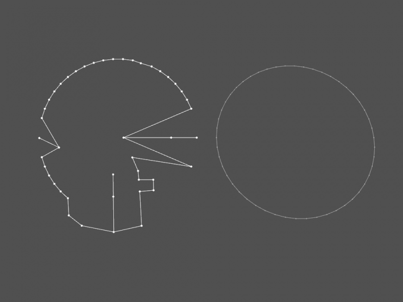
| + | Example of 3 spike events, on point 0, 13 and 25, clockwise culling. | ||
| + | |||
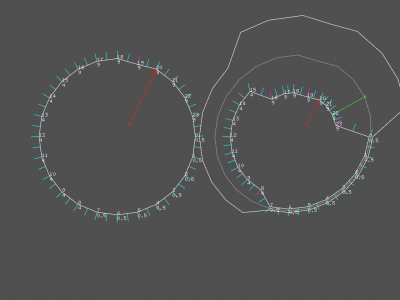
| + | [[File:Spike events 2017062518282511989.png|800px]] | ||
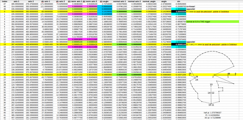
| + | |||
| + | Polygon's points data in CSV format, showing that all spike events have their normal at 0,0. | ||
| + | |||
| + | [[File:Searching the spikes-screenshot.png|800px|link=File:Searching the spikes.ods]] | ||
| + | |||
| + | The detection is implemented in a new kind of event: | ||
| + | |||
| + | template< typename T > | ||
| + | class SpikeEvent { | ||
| + | public: | ||
| + | uint16_t in_index; | ||
| + | uint16_t out_index; | ||
| + | bool crucial; | ||
| + | bool inner; | ||
| + | SpikeEvent() : | ||
| + | in_index( 0 ), | ||
| + | out_index( 0 ), | ||
| + | crucial(true), | ||
| + | inner(true) | ||
| + | { } | ||
| + | }; | ||
| + | |||
| + | These events are created in priority and prevents any other events to occur. Their processing must take place at highest priority when a shrink is requested. | ||
| + | |||
| + | ==== detection ==== | ||
| + | |||
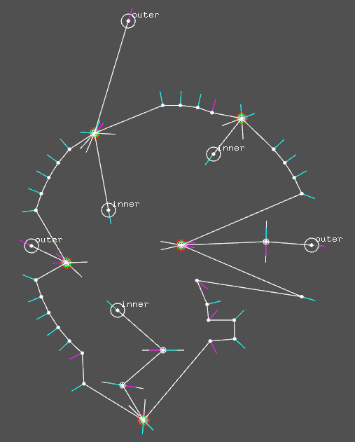
| + | Next step is to identify if the split event concerns inward (shrink) or outward (inflate) offset. First attempt of identification based on direction's normals failed. | ||
| + | |||
| + | [[File:Spikeevents detection.png]] | ||
| + | |||
| + | Detection of spike's direction is quite simple, but requires to travel along the polygon to the "basis" of the spike. This task is performed by using the links between points. Indeed, when a polygon is "link()", each point is connected to its predecessor (pointer to previous) and to its successor (pointer to next). When a point triggers a crucial spike event, the algorithm is looping upwards and simultaneously downwards until it find a pair of points that don't have the same position. All the pairs detected along the process are flagged as minor spike event, implying that they might disappear during spike event processing. It also avoid calculation of more complex events (edge and split) on these points. | ||
| + | |||
| + | When the basis of the spike is found, the spike is declared ''inner'', or ''concave'' if none of the basis points are concave. In other cases (one or both concave), the spike is set to ''outer'', or ''convex''. | ||
| + | |||
| + | Last thing is to create a normal vector for the ''crucial'' spike's event. The detection of spike is based on the fact that normal vector has a length of 0. This is a property of the calculation (to be developed). During the spike detection, the normal of the point is a copy of the previous segment orientation, logically. | ||
| + | |||
| + | Spike curvature is mandatory to manage correctly the shrink process. If the shrink factor is positive (inwards), all ''outer'' spikes have to be removed form the polygon before applying the shrink. Process is reversed when shrink factor is negative (outwards). For the spike having the same orientation as the shrink factor, all ''crucial'' spike's points have to be duplicated and orientated at 45° and -45° of the original point normal. All other values can be kept: the ''minor'' spike's point has already the right informations. This implies creation of a spike event free copy of the current multigon<ref name="multigon">Multigon is a concept used in code to describe a group of polygons. The correct form would be ''multipolygon'', but have been compressed for better code and oral fluidity.</ref> before performing the shrink process. | ||
| + | |||
| + | On coding level, the creation of this copy is tricky, due to the way the normal processing has been split: | ||
| + | |||
| + | * process() < calculation of directions, normals, angles, etc. | ||
| + | ** events() < called automatically, generation of spike, edge and split events | ||
| + | |||
| + | This flow will fired exceptions when two points are at the same position: direction will have zero length, therefore normal vector will have zero length. The creation of two points at the position of a ''crucial'' spike event will end up in the detection of 2 spike events!!! | ||
| + | |||
| + | A more supervised creation method has to be put into place. All work done during process() can be skipped on the copied multigon, because it has already been done on the original. A special treatment has to be applied on ''crucial'' spikes: direction between duplicates is at 90° of the previous one, angles and normal have to computed correctly. | ||
| + | |||
| + | ==== management ==== | ||
| + | |||
| + | <html> | ||
| + | <iframe src="https://player.vimeo.com/video/229914330?title=0&portrait=0&byline=0" width="640" height="360" frameborder="0" webkitallowfullscreen mozallowfullscreen allowfullscreen></iframe> | ||
| + | </html> | ||
| + | |||
| + | [The complete description of the process done during shrink when a shape is flagged as "spiky" will come later.] | ||
| + | |||
| + | Screenshots: | ||
| + | |||
| + | Debugging mode: | ||
| + | |||
| + | [[File:Dc openframeworks spikes 001.png|400px]] | ||
| + | [[File:Dc openframeworks spikes 002.png|400px]] | ||
| + | |||
| + | Clean mode: | ||
| + | |||
| + | [[File:Dc openframeworks spikes 004.png|400px]] | ||
| + | [[File:Dc openframeworks spikes 005.png|400px]] | ||
| + | [[File:Dc openframeworks spikes 006.png|400px]] | ||
| + | |||
| + | There is still a logical error (to be fixed asap), as shown here: | ||
| + | |||
| + | [[File:Dc openframeworks spikes_003_errors.png|400px]] | ||
| + | |||
| + | ==== généralisation (fr) ==== | ||
| + | |||
| + | ===== standardisation des spike events ===== | ||
| + | |||
| + | Je n'utilise les spike events que dans un cas bien particulier pour le moment: lorsque les polygones, au moment où le shrink est appliqué, contient des portions dont les segments sont parallèles ET dont l'extrémité est un angle à +/- 2 pi. | ||
| + | Ce cas équivaut à un event dont le facteur de déclenchement (shrink) est 0, c'est-à-dire un event qui doit être effectué immédiatement, avant de faire quoique ce soit d'autre. | ||
| + | Il existe une autre forme de spike event, plus subtile, une sorte de edge event spécial et dont la condition de détection est très simple: | ||
| + | * si la direction du segment suivant le segment courant est parallèle au segment précédent le segment courant, on peut être certain de le segment courant à de fortes chances de se muer en spike event au cours de l'évolution de la forme. | ||
| + | Ça vaut donc le coup de le détecter à l'avance et de le stocker tout comme les autres types. | ||
| + | Bizarrement, quelque soit l'angle entre le segment courant, le précédent et le suivant, ça n'a que très peu d'importance (si ce n'est l'orientation). | ||
| + | En effet, la somme des angles entre les 3 segments sera toujours pi! | ||
| + | |||
| + | petits croquis en ascii | ||
| + | |||
| + | * cas le plus évident: 2 x angles de 90° | ||
| + | |||
| + | x | ||
| + | p0 _____ p1 | ||
| + | | | | ||
| + | A | | B | ||
| + | | | | ||
| + | <-| |-> | ||
| + | | | | ||
| + | p-1 | ||
| + | |||
| + | À p0, on peut observer que les directions p-1 > p0 et p0 > p1 sont opposées. De là, on stocke un spike event sur p0, et on calcule la distance entre A et B (un peu de math, mais on a déjà les normales, ça devrait aller vite). On divise cette distance par 2 et on obtient le facteur de shrink minimum pour déclencher l'event. | ||
| + | p1 a un statut particulier dans cet event. Il ne s´agit pas d'un point comme les autres (appelés non-cruciaux dans le code). Il ne peut en aucun cas "survivre" au déclenchement de l'event... quoique: dans le cas d'un event ayant la même direction que le spike - convexe dans ce cas, l'intérieur se trouvant entre A et B... non, le spike event de p0 ne déclenchera que vers l'intérieur, p1 est donc condamné à disparaître. | ||
| + | |||
| + | * autre cas | ||
| + | |||
| + | |||
| + | p1 => p0 - p1 | ||
| + | /| => ¦ | ||
| + | x / | B => ¦ B | ||
| + | / |-> => ¦ | ||
| + | / |____________ => ¦____________ | ||
| + | p0 / p2 p3 => p2 | p3 | ||
| + | / => | | ||
| + | | => | | ||
| + | A | => (A) | | ||
| + | | => | | ||
| + | <-| => <-| | ||
| + | ___| => ___| | ||
| + | p-1 => p-1 | ||
| + | |||
| + | dans ce cas, c'est un peu moins rigolo: comme la projection perpendiculaire du point p2 sur la droite p-1,p0 donne un point en dehors du segment |p-1.p0|, il va falloir conserver les 2 points, p-1 et p2. Mais ça revient au même avec des angles carrés: | ||
| + | |||
| + | p0 _____ p1 | ||
| + | | | | ||
| + | A | | B | ||
| + | | | | ||
| + | <-| |-> | ||
| + | | |______ | ||
| + | | p2 | ||
| + | ____| | ||
| + | p-1 | ||
| + | |||
| + | ===== recherche de la base ===== | ||
| + | |||
| + | Comme vu ci-dessus, il est tout-à-fait possible que les deux points "base" d'un spike event ne soit pas identiques et/ou que d'autres points soient alignés des 2 côtés de l'événement. Un autre cas est à traiter: | ||
| + | |||
| + | p0 | ||
| + | . | ||
| + | || | ||
| + | || | ||
| + | p-1 .| | ||
| + | || | ||
| + | p-2 .| | ||
| + | || | ||
| + | |. p1 | ||
| + | p-3 .| | ||
| + | || | ||
| + | || | ||
| + | || | ||
| + | |.________ | ||
| + | | p2 | ||
| + | ____. | ||
| + | p-4 | ||
| + | |||
| + | On identifie de suite les points p-1 et p1, mais il reste à remonter jusqu'à atteindre p-4 et p2. | ||
| + | |||
| + | * cas extrême: | ||
| + | |||
| + | p0 | ||
| + | . | ||
| + | || | ||
| + | || | ||
| + | p-1 .| | ||
| + | || | ||
| + | p-2 .| | ||
| + | || | ||
| + | |. p1 | ||
| + | p-3 .| | ||
| + | || | ||
| + | || | ||
| + | || | ||
| + | . | ||
| + | p2 | ||
| + | |||
| + | |||
| + | * cas similaire topologiquement: | ||
| + | |||
| + | p0 | ||
| + | . | ||
| + | // | ||
| + | // | ||
| + | // | ||
| + | p-1 .. p1 | ||
| + | || | ||
| + | || | ||
| + | || | ||
| + | . | ||
| + | p-2 = p2 | ||
| + | |||
| + | La différence dans ce cas est la présence de point identiques, et l'obligation de prendre en compte le fait que le polygone contienne un nombre pair ou impair de points. Ce cas limite, où le point le plus éloigné est présent aux 2 extrêmités du spike, permet de flagger le polygone comme étant une ligne, n'ayant plus du coup que la faculté de s'étendre (shrink négatif uniquement, donc). | ||
| + | |||
| + | Ce qui nous amène à une constation intéressante: du point de vue de l'algorithme, une ligne est un polygone sans surface, n'ayant donc pas d'"intérieur". | ||
| + | Cette faculté nous permettra de charger des les chemins ouverts du fichier svg, en doublant tous les points sauf le premier! En prime, ça nous donne la garantie que le premier point sera un split event qui parcourera toute la forme, empêchant du même coup la possibilités et donc le calcul de tous les autres types d'événements. | ||
| + | |||
| + | Les spikes sont des événements cruciaux pour les straight skeletons. | ||
| + | |||
| + | Dernier cas d'utilisation des spikes: détection des collisions de segments parallèles. | ||
| + | |||
| + | ___ / | ||
| + | | | | ||
| + | | | | ||
| + | |____| | ||
| + | |||
| + | ________ | ||
| + | | | | ||
| + | | | | ||
| + | | | | ||
| + | / \ | ||
| + | |||
| + | === Weights === | ||
| + | |||
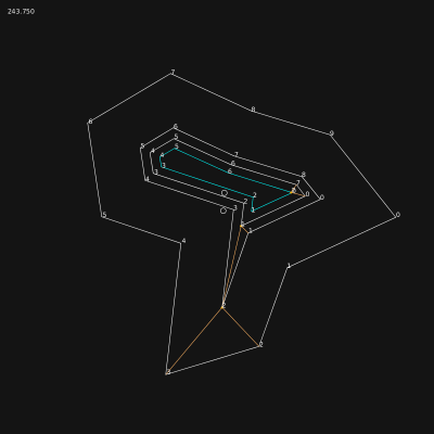
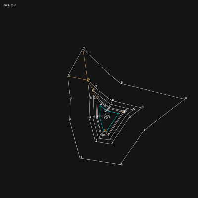
| + | The straight skeleton<ref name="straight skeleton"/> being used here to generate the borders of the roads and the shapes of the building, it has been clear early in the development that the polygon's segments might react differently to the shrink factor. Each side of a polygon represents a portion of road. The road, depending on its importance, might have a different width. When the shrink is process, this differences of width generate discontinuities in the ''speed'' of the segments. The ''weight'' of the segment represents this idea, and is used as a multiplier on the shrink factor requested. | ||
| + | |||
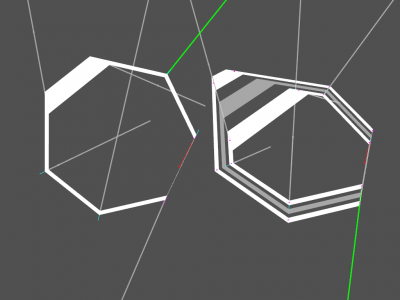
| + | [[File:Roadmap 201707061021419509.png|400px]] | ||
| + | |||
| + | This image represents the difference of weight on different segment of the polygon. On the right, higher weights implies a bigger translation of the segment. | ||
| + | |||
| + | [[File:Roadmap 2017070612531292040.png|400px]] [[File:Roadmap 20170706130009106809.png|400px]] | ||
| + | |||
| + | Events have to take the weight into account. A part of the work has been done on the split events, but the results are still buggy, see blue polygon on second and third screenshots. | ||
| + | |||
| + | [[File:Roadmap 20170706132100108370.png|400px]] [[File:Roadmap 20170706132149156872.png|400px]] [[File:Roadmap 20170706132154162684.png|400px]] | ||
| + | |||
| + | == Export/import == | ||
| + | |||
| + | CSV and SVG exports are available (to be documented). | ||
| + | |||
| + | [[File:Darkcity csv svg exports.png|400px]] | ||
== References == | == References == | ||
| Line 707: | Line 1,104: | ||
* '''Doubly connected edge list''', also known as half-edge data structure - [[wikipedia:Doubly_connected_edge_list|wikipedia]] | * '''Doubly connected edge list''', also known as half-edge data structure - [[wikipedia:Doubly_connected_edge_list|wikipedia]] | ||
* ''Segments' intersection'' & ''Segments' crossing'' in [[Notes:Math|Notes:Math]] | * ''Segments' intersection'' & ''Segments' crossing'' in [[Notes:Math|Notes:Math]] | ||
| + | * ''Paths: Stroking and Offsetting'' http://tavmjong.free.fr/blog/?p=1257 | ||
| + | |||
| + | === related === | ||
| + | |||
| + | <html><iframe width="560" height="315" src="https://www.youtube.com/embed/xhj5er1k6GQ" frameborder="0" allowfullscreen></iframe></html> | ||
| + | |||
| + | Solving via the 3rd dimension: | ||
| + | |||
| + | <html><iframe width="560" height="315" src="https://www.youtube.com/embed/6xxHrWaTAAo" frameborder="0" allow="autoplay; encrypted-media" allowfullscreen></iframe></html> | ||
| + | <html><iframe width="560" height="315" src="https://www.youtube.com/embed/oLM99qYnzm0" frameborder="0" allow="autoplay; encrypted-media" allowfullscreen></iframe></html> | ||
[[Category:Disrupted Cities]] | [[Category:Disrupted Cities]] | ||
| Line 721: | Line 1,128: | ||
[[Category:processing.org]] | [[Category:processing.org]] | ||
[[Category:openframeworks.cc]] | [[Category:openframeworks.cc]] | ||
| + | [[Category:javascript]] | ||
Latest revision as of 20:52, 25 July 2018
This page describes the different steps implemented in the city generator package to detect block in the road's network, in a fast and clean way.
Contents
repo(s)
sketches
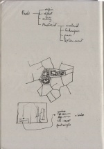
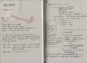
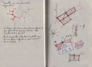
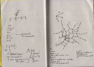
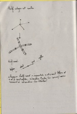
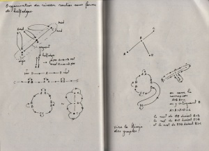
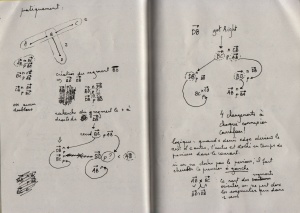
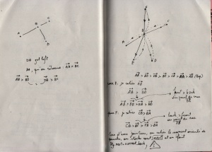
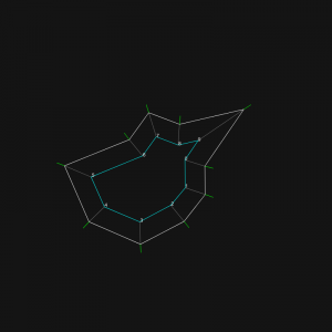
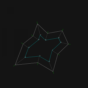
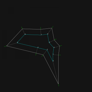
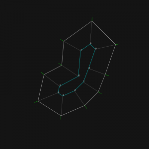
These sketches cover the whole research described below. They are displayed chronologically.
block detection
right vector
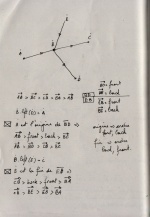
Finding the closest road on the right at a crossroad[1].
To generate the bocks of building based on the roads structure, the method I’m building is based on a simple idea: when you arrives at a crossroad, you take the first street on the right and you go on like this until you reach a dead-end or your starting point. If you reach your starting point, the succession of roads you took defines a block of building. In theory. This technique has been suggested by Michel Cleempoel, on the way back from school.
After a bit of preparation of the road network (removing orphan roads, having no connection with others, and dead-ends parts of the roads), the real problem arouse: how do you define right in a 3d environment, without an absolute ground reference. Indeed, I can configure the generator to use the Y axis (top axis in ogre3d) in addition to X & Z.
At a crossroad, you may have several possibilities of roads. In the research, these possible roads are reduced to 3d vectors, all starting at world’s origin. The goal is to find the closest vector on the right of the current one, called the main 3d vector in the graphic above..
The right is a complex idea, because it induces an idea of rotation. The closest on the right doesn’t mean the most perpendicular road on the right side. Let say I have 4 roads to choose from. Two going nearly in the opposite direction of the road i’m on, one perpendicular and one going straight on.
If I compute the angles these roads have with the current one, results are:
- 5°,
- -5°,
- 90°,
- and 170°.
The winner is not the 90°, but the 5° road! If I sort them, the last one must be the -5°, who is the first on the left.
3d plane from a 3d vector
The first thing to do is to define reference plane. To do so, you get the normal vector of the road by doing a cross product with the UP axis (Y axis in this case). The normal gives you a second vector, perpendicular to the road, and therefore defines a plane. Let’s call it VT plane, for Vector-Normal plane. For calculation, we need the vector perpendicular to this plane, rendered by crossing the road and its normal, let’s call it the tangent vector. Until here, it’s basic 3d geometry.
projection of 3d vectors on a plane
We can now project all the possible roads on the VT plane. These are the yellow vectors in the graphic. The math are clearly explained by tmpearce[2]. Once implemented, it looks like this:
float d = othervector.dot( tangent );
vec3f projectedvector;
projectedvector += tangent;
projectedvector *= d * -1;
projectedvector += othervector;
We are nearly done!
angle between 3d vectors
The projected vectors will help the angle calculation. Indeed, the current vector and the projected ones being coplanar, they share the same normal. The way to get the angle between 2 coplanar vectors is described by Dr. Martin von Gagern[3], once again. See Plane embedded in 3D paragraph for the code i’ve used.
And… tadaaammmm! The number rendered by the method is the angle i was searching for, displayed in degrees in the graphic above.
The c++ implementation of the method is looking like this:
RDListIter it;
RDListIter ite;

vec3f dir = ( *from )-( *this );
vec3f normal = GLOBAL_UP_AXIS.getCrossed( dir );
normal.normalize( );
vec3f tangent = dir.getCrossed( normal );
tangent.normalize( );

it = connected_dots.begin( );
ite = connected_dots.end( );

RoadDot* sel_dot = 0;
float smallest_angle = -1;

for (; it != ite; ++it ) {

    if ( (*it) == from ) {
         continue;
    }

    vec3f nv = ( *( *it ) )-( *this );
    nv.normalize( );

    // http://stackoverflow.com/questions/9605556/how-to-project-a-3d-point-to-a-3d-plane#9605695
    float d = nv.dot( tangent );
    vec3f nn = nv + tangent * d * -1;

    // http://stackoverflow.com/questions/14066933/direct-way-of-computing-clockwise-angle-between-2-vectors
    float dot = nn.x * dir.x + nn.y * dir.y + nn.z * dir.z;
    float det =
              nn.x * dir.y * tangent.z +
              dir.x * tangent.y * nn.z +
              tangent.x * nn.y * dir.z -
              nn.z * dir.y * tangent.x -
              dir.z * tangent.y * nn.x -
              tangent.z * nn.y * dir.x;

    float angle = atan2( det, dot );

    if ( angle < 0 ) {
         angle += TWO_PI;
    }

    if ( sel_dot == 0 || smallest_angle > angle ) {
         sel_dot = ( *it );
         smallest_angle = angle;
    }

}

return sel_dot;
- RDListIter is a typedef vector<RoadDot*>
- GLOBAL_UP_AXIS allows to define wich is the UP axis of the world.
- vec3f is a standard class for 3d vector manipulation, depending on your framework.
half-edges[4]
See method chapter for a resume of the implementation.
Isle::collect_oriented_segments(Road* r)
cases to foresee:
0. starting the road, previous dot has one connection
1. starting the road, previous dot has >1 connections > crossroad
2. along the road, current dot has two connections
3. along the road, current dot has >2 connections > crossroad
4. end of the road, current dot has one connection
5. end of the road, current dot has >1 connections > crossroad

A       B       C
o ----> o ----> o
        ^
        |
        |
        D

[f]  [f]  [b]  [b]  [f]
AB > BC > CB > BA > AB

[f]  [b]  [f]  [f]  [b]  [b]  [f]
AB > BD > DB > BC > CB > BA > AB


A       B       C
o ----> o ----> o
        |
        |
        v
        D

[f]  [f]  [b]  [f]  [b]  [b]  [f]
AB > BD > DB > BC > CB > BA > AB

cases [2,5] can happens simultaneously
It seems nearly impossible to create the relation between half-edges correctly in one pass: some half-edges tries to connect to not yet created half-edges. If the half-edges are generated on the fly, it will imply a check at each half-edge (HE) generation, to validate if the HE is already created or not.
A better approach seems to be: generation of all of them + creation of structures for crossroads, holding a pointer to the RoadDot and the list of all HEs connected to it. Connections can be resolved locally in a second pass. Let's try it.
Not yet functional: blocks are crossing roads...
The issue was coming from a method that sort the connections of a roaddot: RoadDot::rightSort(RDList& sorted). In its first implementation, I was just looping over the connections and storing in a list the result of the method RoadDot::getRight(RoadDot* from);, without checking in any way the angles between these dots. The block crossing street issue was caused by this inconsistency. I now use a skip list and I always use the first connection as a reference. Code is simple:
void RoadDot::rightSort( RDList& sorted ) {

   RDListIter it = connected_dots.begin( );
   RDListIter ite = connected_dots.end( );

   sorted.push_back( connected_dots[0] );
   RDList skip;
   skip.push_back( connected_dots[0] );

   for(; it != ite; ++it ) {
       RoadDot* d = getRight( connected_dots[0] , skip );
       if ( !d ) break;
       skip.push_back( d );
       if ( find( sorted.begin(), sorted.end(), d ) != sorted.end() ) {
           cout << "Double push in sorted!!!" << endl;
       }
       sorted.push_back( d );
   }

}
Each time a dot on the right is retrieved, it is added to the skip list for the next search. Sorting, in a word...
Algorithm can be very painful... but when they are logically correct, they work marvellously! The generation time of each map is nearly unchanged, and results are perfect: no holes!
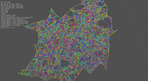
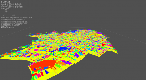
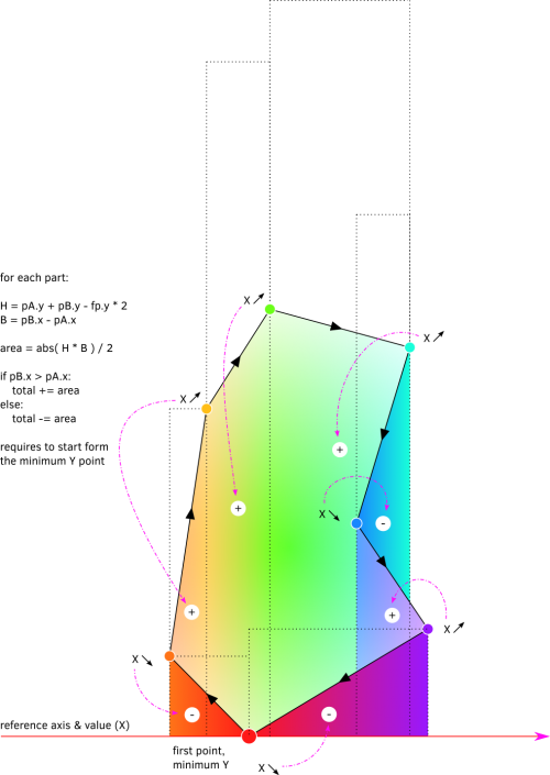
Last screenshot shows the block rendered as plain shapes. The big yellow one is the outer bound of the map! With a method to measure surfaces of a random polygon, I'll be able to have the precise city area.
method
The first implementation of block detection was using the road's segment. The algorithm was starting with the 2 first dots of the first road and was travelling across the network by performing a getRight() at each dot having more than 2 connections.
A --- B ---- C ---- E
             |
             |
             D
A: {B}
B: {B,C}
C: {B,D,E}
E: {C}
The main issue of this method was that some blocks were not detected! Each time I was passing by through a dot, I was storing wich connections I used. In some cases, the dot needed to be used one time more than its number of connection.
A much better way to perform the search for blocks is based on the half-edges[4] technique. Indeed, each block uses a serie of half-edges, and these half-edges are used only by it. This approach is similar to directed graphs[5].
Any point of the map is a RoadDot, looking like this:
class RoadDot {
public:
   float x;
   float y;
   float z;
   vector<RoadDot*> connected;
I now using a specialised class for half-edges:
class OrientedSegment {
public:
   RoadDot* from;
   RoadDot* to;
   OrientedSegment* next;
and a class knowing wich half-edges are connected to wich dot:
class CrossRoad {
public:
   vector<OrientedSegment*> arriving; // ending at the key 'roaddot'
   vector<OrientedSegment*> leaving; // starting the key 'roaddot'
The crossroads are stored in a map< RoadDot*, CrossRoad >.
Getting all the half-edges at a given dot is now really easy: you pick the crossroad by looping on dots, and I get 2 lists of half-edges connected to the dot.
The OrientedSegment are generated during roads generation. Once the road's network is built, I run a method to connect all half-edges to each other.
The method is looking like this:
RoadDot* d = (*it); // 'it' is an iterator looping over all roaddots of the network
CrossRoad& cr = crossroads[d]; // the crossroad list, of type map< RoadDot*, CrossRoad >

if ( d->connected.size( ) == 1 ) {

   cr.arriving[ 0 ]->next = cr.leaving[0];

} else if ( d->connected.size( ) == 2 ) {

   cr.arriving[ 0 ]->next = cr.leaving[1];
   cr.arriving[ 1 ]->next = cr.leaving[0];

} else {

   vector<RoadDot*> sorted_dots;
   d->rightSort( sorted_dots );
   RDListIter first = sorted_dots.begin( );
   RDListIter next = sorted_dots.begin( );
   ++next;
   RDListIter it = sorted_dots.begin( );
   RDListIter last = sorted_dots.end( );

   OrientedSegment* os_arriving = 0;
   OrientedSegment* os_leaving = 0;

   for (; it != last; ++it, ++next ) {

       if ( next == last ) {
           next = first;
       }

      os_arriving = cr.getArriving( ( *it ) );
      os_leaving = cr.getLeaving( ( *next ) );
      os_arriving->next = os_leaving;

   }
}
After this, all half-edges are connected on each other correctly. Detecting blocks is a ultra-simple:
OrientedSegment* start = os;

Block* b = new Block( );

while ( os->next != start ) {

   b->add( os->from );
   os->blocked = true;
   os = os->next;

}
surfaces
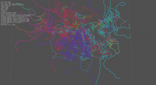
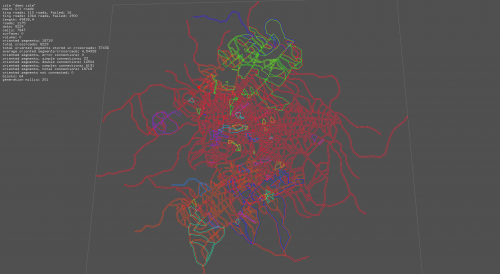
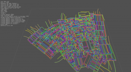
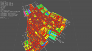
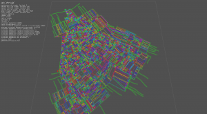
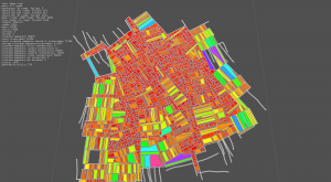
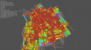
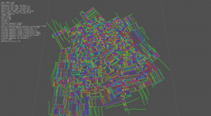
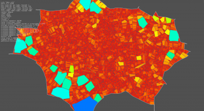
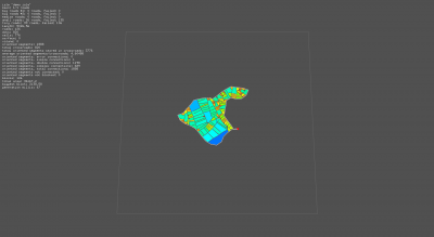
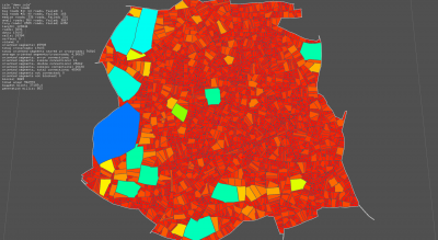
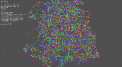
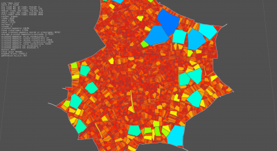
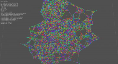
The implementation of the method has been rather quick, even if the results have to be better checked, via a comparaison with a bounding box for instance. The color mapping in the screenshots below is as follow:
- surface ∈ [0,3000]: ( bigger => violet & more grey )
- hue: [0,3000] → [0,255]
- saturation [0,3000] → [255,180]
- huge surface (>=3000): white stroke
Image are 1920x1080, click on them to see details.
Legend:
- image #1: block's color depends on surface, roads are displayed as white lines
- image #2: block's color depends on surface, roads are not displayed
- image #3: block outline, a small cross indicates the center of each block
Reviewing surface calculation process > there was an inversion of axis in the computation, and it was missing absolute methods at several places. Surface is validated against the bounding box area. Before corrections, the surface was bigger than the bounding box...
Large and small network.
Fill and stroke of the same map.
Fill and stroke of the same map.
There is a strange cutted edges on a lot of blocks. The block detection must miss a dot in several cases... I hope the bug is not in the half-edges linkage. Must be investigated.
shrinking
After detection, blocks are 'glued' to roads. An offset has to be applied on the shape in order to leave some space for the road itself. The first approach used was to shrink the shape by applying an offset of x along each dot normal. Calculation of the normal is straight forward: perpendicular of the previous segment direction + perpendicular of the next segment direction divided by 2. In pseudo code, it gives:
vec3f previous_dir = (current_dot - previous_dot).cross( UP );
vec3f next_dir = (next_dot - current_dot).cross( UP );
vec3f normal = ( previous_dir.normalised() + next_dir.normalised() ).normalised();
normalised() returns a normalised copy of the vec3f
This approach was not keeping the segment's orientation. The shape was distorted.
Straight Skeletons[6]
The method of Peter Palfrader called Computing Straight Skeletons by Means of Kinetic Triangulations[7] is proposing a way to solve this y using wavefront propagation.
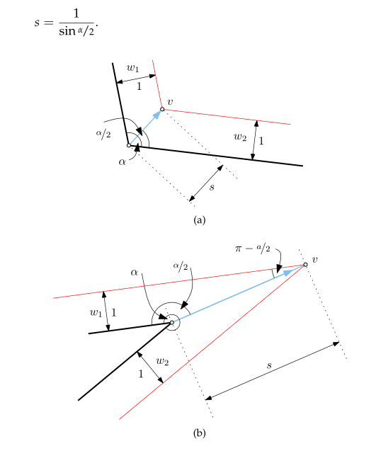
First step is to move the dots in a way to keep the road segment and the block segment parallel. The math to perform is clearly explained in the thesis, page 14[7].
Calculation of s, in pseudo-code:
float a = atan2( normale.y, normale.x ) - atan2( previous_dir.y, previous_dir.x );
vec3f shrink_dot = dot + normale * ( 1 / sin( a ) * 0.5 ) * distance;
Java (processing) implementation, with mouse control on the shrinking:
PVector UP = new PVector( 0, 0, 1 );
PVector[] points;
PVector[] normals;
float[] angles;
int num;

void setup() {
 size( 800, 800 );
 num = 10;
 points = new PVector[ num ];
 normals = new PVector[ num ];
 angles = new float[ num ];
 generate();
}

void generate() {
 for ( int i = 0; i < num; ++i ) {
   float a = TWO_PI / num * i;
   float r = random( width * 0.1, width * 0.47 );
   points[ i ] = new PVector( cos(a)*r, sin(a)*r );
 }
 for ( int h = num-1, i = 0, j = 1; i < num; ++h, ++i, ++j ) {
   if ( j >= num ) {
     j = 0;
   }
   if ( h >= num ) {
     h = 0;
   }
   normale( i, points[ h ], points[ i ], points[ j ] );
 }
}

void normale( int i, PVector before, PVector p, PVector after ) {
 PVector dirbefore = new PVector( p.x - before.x, p.y - before.y );
 dirbefore.normalize();
 PVector nbefore = dirbefore.cross( UP );
 nbefore.normalize();
 PVector dirafter = new PVector( after.x - p.x, after.y - p.y );
 dirafter.normalize();
 PVector nafter = dirafter.cross( UP );
 nafter.normalize();
 PVector n = new PVector();
 n.add( nbefore );
 n.add( nafter );
 n.normalize();
 normals[i] = n;
 angles[i] = atan2( n.y, n.x ) - atan2( dirbefore.y, dirbefore.x );
}
void draw() {
 float m = ( ( mouseX * 1.f / width ) - 0.5 ) * width;
 background( 20 );
 pushMatrix();
 translate( width * 0.5, height * 0.5 );
 for ( int h = num-1, i = 0, j = 1; i < num; ++h, ++i, ++j ) {
   if ( j >= num ) {
     j = 0;
   }
   if ( h >= num ) {
     h = 0;
   }
   stroke( 255 );
   line(
     points[ i ].x, points[ i ].y,
     points[ j ].x, points[ j ].y
     );
   stroke( 0, 255, 0 );
   line(
     points[ i ].x, points[ i ].y,
     points[ i ].x + normals[i].x * 20, points[ i ].y + normals[i].y * 20
     );
   PVector proi2 = new PVector(
     points[ i ].x + normals[ i ].x * ( 1 / sin( angles[ i ] ) * 0.5 ) * m,
     points[ i ].y + normals[ i ].y * ( 1 / sin( angles[ i ] ) * 0.5 ) * m
     );
   PVector proj2 = new PVector(
     points[ j ].x + normals[ j ].x * ( 1 / sin( angles[ j ] ) * 0.5 ) * m,
     points[ j ].y + normals[ j ].y * ( 1 / sin( angles[ j ] ) * 0.5 ) * m
     );
   stroke( 0, 255, 255 );
   line( proi2.x, proi2.y, proj2.x, proj2.y );
   stroke( 255, 100 );
   line( proi2.x, proi2.y, points[ i ].x, points[ i ].y );
   fill( 255 );
   text( i, proi2.x, proi2.y );
 }
 popMatrix();
}

void keyPressed() {
 if ( key == 'g' ) {
   generate();
 } else if ( key == 's' ) {
   save( "straightskeleton_" + year() + "" + month() + "" + day() + "" + hour() + "" + minute() + "" + second() + ".png" );
 }
 println( key );
}
Results are good:
Edge events
The next steps is to locate edges events and split events.
The edges events can be detected easily: the space between 2 points is 0, or the orientation of the shrinked segment is inverted.
Inversion of a vector can be detected like this:
vec2f dir_origin = a¹b¹.normalised();
vec2f dir_shrink = a²b².normalised();
if ( dir_origin.dot( dir_shrink ) < 0 ) {
    // FLIP!
}
Detection of edges events (called flips in the code).
Approach: a first attempt is performed to shrink the shape at the requested factor. One processed, the generated edges directions are compared to the original shape. If some edges directions are opposite to the originals, I retrieve the intersection between the 2 segments linking the origins to the generated points.
a ------------> b (original segment)
 \             /
   \         /
     \     /
       \ /
        i
       / \
     /     \
    b² <--- a² (generated segment, opposite direction)
A new shape is produce in witch the point a and b are merged, becoming i.
The possible factor for this pass is equals to:
possible_factor = factor * length( a,i ) / length( a, a² )
A new shrink attempt is performed on basis of the new shape, in wich a & b are merged into i, by a factor of orginial_factor - possible_factor.
It's not going too bad, but the process is still very unstable.
The lack of split events management is provoking this kind of issues:
The point 0 should not be allowed to cross the edge 4,5, and 2 sub polygons should be produced to finish the shrink process.
The method used until now was to try to go to the target factor and check, once applied, if there was issues. If yes, a rollback was performed to the first edge event. A new polygon was generated and a new test performed and so on until the target factor was reached. Shrinking this way causes issues when the shrink factor was far above the maximum (aberrations occur), or the factor between 2 edge events was too small.
In short: trying to go somewhere, hitting a wall on the way and only than seeking a door. It is a bit too stupid to hope the algo will behave in a consistent way...
Edge events are located at the intersection of the dots' normal. Finding them is easy, especially when you already have a method to process intersections of lines and segments [8]. Some of the intersections are pointing toward the center of the shape, others outward. I called this property inner. To render it, I have to verify if the intersection is on the right or left side of the vector.
vec2f cross_point, segment_start, normal_start, segment_end, normal_end;
bool inner;
cross_point = intersection( segment_start, segment_start + normal_start, segment_end, segment_end + normal_end );
inner = ( normal_start.dot( cross_point - segment_start ) < 0 );
All intersections are detected successfully:
Legend: orange dots are pointing inward, blue ones outward.
Next step is to choose the first intersections that the shrinking shape will meet. The inner marker is very useful in this respect:
- when going outward (negative factor), the blue intersections must be tested;
- when going inward (positive factor), the orange intersections must be tested.
The question of what is the shrinking factor corresponding to this intersection? quickly arouse. We have to inverse the s calculation (see straight skeleton chapter) in this way:
vec2f cross_point, segment_start;
float angle_start;
float intersection_factor = cross_point.dist( segment_start ) /  ( 1 / sin( angle_start ) * 0.5 );
Once done, we just have to pick the smallest intersection factor depending on the factor sign. We can now anticipate the edge events, before making an attempt to shrink.
If shrink factor is less than the smallest intersection factor:
If the shrink factor is high, new polygons are generated on the way, each one containing a reference to the first edge event.
Due to the lack of split event (the next challenge), there are still huge glitches in the process:
Split events
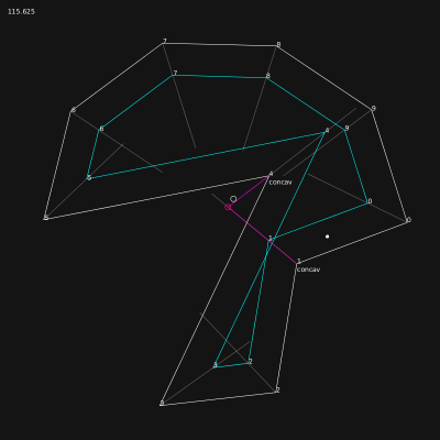
Anticipation of split events requires some brain power.
In the first try, I was computing the intersections between concave angles ( > 180°) and all the segments of the shape. It was nice, in a static shape. But when you shrink a shape, ALL points move, implying that pair point-segment you selected might not be the one where the split event will occur! The prediction was functional, but essentially wrong.
After a cigaret, a full album of the the Mamas & the Papas[9], some sketches on paper and a sketch on inkscape, a simple solution appeared:
- computing the intersections between concave angles' normal and vector prepared for edge events;
- keeping the intersection where
- distance to its origin is the smallest and
- direction is opposite to the normal (to validate).
Colors are inverted in the images below, regarding the color code described in edge events.
The method currently in test is based on intersections between angle bisectors, same approach as the edge events.
During polygon generation, all bisectors are tested on all others, in a separated pass. Bisectors are opposite to the normal vector, this is why you will find - normal in the code below.
Process done at each test:
// finding the intersection between > lines <!
vec2f i = intersection( other.x - other_normal.x, other.y - other_normal.y, current.x - current_normal.x, current.y - current_normal.y );
// verifying that inyersection is inside the shape
if (
   vec2f( i.x - other.x, i.y -  other.y ).cross( other_normal ) > 0 ||
   vec2f( i.x - current.x, i.y -  current.y ).cross( current_normal ) < 0 ||
) {
   // OUTISIDE!
} else {
   // getting the length of the current-intersection segment
   float tmpd = vec2f( i.x - other.x, i.y -  other.y ).length() / abs( 1 / sin( other_angle ) * 0.5 );
   if ( tmpd < current_smallest_dist ) {
      split_pint = i;
   }
}
It is not yet correct: the intersction is inside the shape, ok, but the closest intersection is rarely the good one. Speed is not correctly implemented.
It seems that speed have to be taken into account more seriously. All points move together, meaning that the angle difference between the points influences the crossing time. The more opposite the angles are, the fastest they will cross each other.
Distance and speed have to influence the intersection choice.
Current calculation is not correct. In the first screenshots above, the first split event happens between point 4 and segment 8-9. If 4 is moved a bit, the first split event happens between point 1 and segment 3-4.
Observations:
- case #1: intersection involves segment 0-1
- case #2: intersection involves segment 1-2
- case #3: intersection involves segment 6-7, even if the bisector is crossing the segment 7-8
Resume of the system to resolve.
Basic computation for split events is ok. The red circle in screenshots below shows the predicted split event position. The second screenshot has been generated by manually adjusting the shrink value. The red point and the actual split event occur at the same location.
The math to find the point is based on a line / segment intersection detection. The line is the bisector of the concave point. All polygon's segments are tested against this line. If an intersection is detected, the distance between the concave point has to be divided.
// vec2f ptA // segment point a
// vec2f ptB // segment point b
// vec2f concave_point // position of concave point
// vec2f concave_normal // normal of concave point
// float concave_angle // angle of concave point
vec2f intersc = intersectionSegmentLine( ptA, ptB, concave_point, concave_point + concave_normal);
if ( intersc ) {
    float distance = sqrt( pow( intersc.x - concave_point.x, 2 ) + pow( intersc.x - concave_point.x, 2 ) );
    float split_distance = distance / ( 1 + sin( PI + concave_angle ) )
    vec2f split_point = concave_point + concave_normal * split_distance;
}
There is still some work to be done, simultaneous split events for instance, or segment's swap when too close from a border, see observations here above.
With a little help from my friend[10], the calculaton is finally perfect. Indeed, the angle between the bisector and the segment influences the division of the distance between the concave point and the intersection.
If the segment is perpendicular to the segment, the form: File:Split-event-anticipation01.png
distance / ( 1 + sin( PI + concave_angle ) )
is correct. But as soon the bisector has a slight angle, the allowed shrink factor has to be reduced by the sinus of the angle between the bisector and the segment.
I had to rebuild a simple processing[11] sketch to fix this.
The core of the process lies in these lines:
float d = concav.dist( intersect );
float dr = d / ( 1 + ( 1 / sin( concav.angle ) ) * ( sin( intersecta ) ) );
float dd = d - dr;
PVector evsp_point = new PVector(
    concav.x + concav.normal.x * dd,
    concav.y + concav.normal.y * dd
);
This gives the intersection point, not yet enough to trigger the split event. It has to be finished with this:
max_factor = dr * sin( intersecta );
It works perfectly! In the sketch, I automatically reduce factor to max_factor, result is always good.
selection
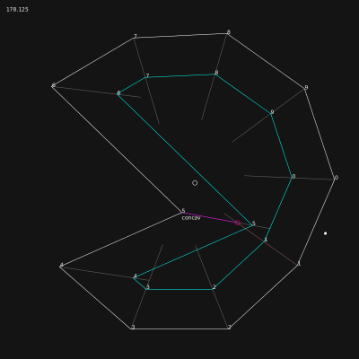
The selection of the first split event for a specific point is much more tricky than expected.
In the case below, the bisector of the sharp angle do not cross the closest segment. The selection process remove the segment from the candidates. Result is dramatic: during shrink, this segment will cross the bisector! Anticipation is not correctly processed.
The graph below shows a way to fix this. Let's call the point with the orange bisector the current point.
Split event selection process for the current point, step by step:
- segment normal dot current bisector is less than 0 > segment is out, the segment is oriented towards the current point, implying that another segment leading this one will cross the bisector closer > green intersection is removed;
- if intersection point between segment and current bisector is in segment > already solved by current code > blue intersection is processed;
- if intersection point between segment and current bisector is not in segment (pink intersection), do one of the bisectors of segment points cross the segment formed by current point and intersection point?
- if yes > the segment, dragged by its point, will certainly cross the bisector at one point during shrink! > orange intersection is valid > pink intersection is processed;
- if no > continue;
- last test concern the distance evaluation: the closest intersection must be kept, but in the case of outside crossing, the intersection has to be moved much closer from the current point, and the factor to apply depends on the angle of the bisector crossing the [current, intersection] segment.
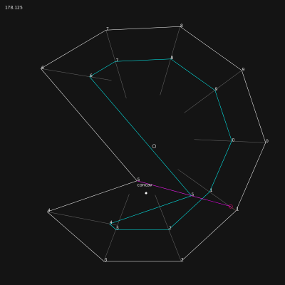
Better selection of split event is implemented. The problem case here above is solved. Algorithm has changed a bit.
Operations:
- if normal of the segment is not in the same direction has the current bisector, skipping segment
- retrieval intersection between bisector and line passing by the 2 points
- if intersection is not in the same direction as the current bisector, skipping segment
- calculation of intersection position, same as before
- if intersection happens outside of the segment and none of the normals of segment points cross the current bisector, skipping segment
- if there is already a split event detected for the current point and the shrink factor is higher than the previous event, skipping segment
- storage of the event if all conditions are ok
- once done, if an edge event exists for the current point, deletion of the split event
Note that tests 1, 3 & 5 are inverted for outer events.
Limitations
There are still logical mistakes at step 5 of the algorithm. The exact test is this one:
bool pi_inter = false;
pi_inter = (
    (pu.concav && pi.shrink_multiplier > pu.shrink_multiplier) ||
    (!pu.concav && pi.shrink_multiplier < pu.shrink_multiplier)
);
if (pi_inter) {
    pi_inter = Geometry<T>::intersection(
        pi, pi_and_normal,
        pu, ii.result,
        ii.result,
        false, true);
}
Lines 3 & 4 test the shrink_multiplier of pu (current point) and pi, one of the segment's point. The shrink_multiplier is eqivalent to the speed of point, it is used to multiply the factor passed to the Multigon::shrink() method. The concav parameter is used to know if the event happens when shrinking or inflating the polygon. The idea was to only test the crossing of the normal and the bisector if the segment point is going 'faster' than the current point. This leads to errors in split event selection, shown here below.
The problem is clear: the test forces the selection of the point having the biggest shrink_multiplier, without taking into account other facts, such has the distance of the intersection, etc.
After a bit of brain juice spread on paper, the resolution of the problem became obvious. If the split event happens outside of the segment, the split event is kept if the current point is the last to reach the intersection between bisectors. It's a basic math problem...[12]
Inner split events are now ok, but there is still some issues on the external selection. This shapes does not behave nicely on outer split. On the right side, cyan polygon, in the first case, and on the left (green polygon) in the second. The split event is triggered from the wrong point.
Solved in 2 minutes: error was due to a stupid inverted test on distance for outer splits...
Simplier version (p5.js)
One of the big problem in split event detection is when the bisector of the point is not crossing the segment (see selection of segment for details).
The first implemented method was based on detection of bisectors' intersection. The method is unsafe. A better method is to create a temporary polygon representing the surface covered by the segment when shrunk, and verify that the event point is belonging to the surface.
It has been implemented in this sketch ():
manipulation:
- right-click & drag points to move them
- right-click & drag anywhere else to modify offset
C++
It was time to leave Java and re-implement the methods in C++. I'm working in openfremworks to prepare the library. The classes processing the polygons are 100% independent from OF's one, even the vector3 class. Details of the code will be done once the lib will be finished.
The important idea is to use a **Multigon** object, able to manage several polygon. It will be very useful when split events will occur. It also allows to cut into smaller polygon a self-intersecting polygon.
For the moment:
- multiple edge events are managed correctly &
- polygon grows or shrink smoothly.
In the current vetrsion, several improvements have been done:
- new event collapse, indicates when a shape is too small to be shrinked;
- when a shape collapse, the position of its center is kept along the shrink steps;
- concurrent events (collapse, edge & split) are managed correctly in different subparts of the general shape;
- and the whole is not crashing anymore (!).
There are still errors in split events calculations, as shown in the video. Once done, the next worksite will focus on shapes with sharp spikes, when the angle between 2 segments is equal to 360°.
After refining split event selection process, shrink can be performed on complex shapes. Screenshots below are random generated shapes with 100 points.
video
Visual syntax:
- left polygon is the original shape to shrink;
- result of the process is display on the right;
- each time an "event" occurs, a trail is left behind.
- once a polygon is split, each part of it gets a different color;
- stable red lines shows where the first edge event will happen;
- green & magenta lines shows where the first split event will happen.
2.5d
With minor adjustements, code is now able to process 3d polygons as 2d shapes. The UP axis component is removed form the shrink calculation but is kept for final output.
Demo:
On the last image, the lack of an average on the UP axis during edge events implies huge discontinuities in the shape.
Edge & split events results are now smoothed on UP axis. In images below, a highly randomised polygon with 200 points is shrink correctly, but the processing time is growing too fast to allow this kind of manipulation in real-time.
Demo:
Spike events
description
The code being more and more stable, even if a good cleanup in data structures is required (management of events and check of unnecessary fields in objects, points especially), it's the right time to start the implementation of a new kind of events. I've identified them nearly two month ago, and because they are not mentioned in the study of Peter Palfrader[7], I named them spike event. For humans, a spike event is a part of the polygon looking as a line, or a needle.
A spike event occurs when:
- the computed normal of the point has its 2 axis at 0 (the up axis is not taken into account, we are working in 2.5d);
- when two points have the same position and are connected to a point of the first kind.
In the first case, the event is flagged as crucial and has a reference to the first point leading to him and not being a spike event and the last point connected to him and being a spike event.
Example of 3 spike events, on point 0, 13 and 25, clockwise culling.
Polygon's points data in CSV format, showing that all spike events have their normal at 0,0.
The detection is implemented in a new kind of event:
template< typename T >
class SpikeEvent {
public:
    uint16_t in_index;
    uint16_t out_index;
    bool crucial;
    bool inner;
    SpikeEvent() :
       in_index( 0 ),
       out_index( 0 ),
       crucial(true),
       inner(true)
    { }
};
These events are created in priority and prevents any other events to occur. Their processing must take place at highest priority when a shrink is requested.
detection
Next step is to identify if the split event concerns inward (shrink) or outward (inflate) offset. First attempt of identification based on direction's normals failed.
Detection of spike's direction is quite simple, but requires to travel along the polygon to the "basis" of the spike. This task is performed by using the links between points. Indeed, when a polygon is "link()", each point is connected to its predecessor (pointer to previous) and to its successor (pointer to next). When a point triggers a crucial spike event, the algorithm is looping upwards and simultaneously downwards until it find a pair of points that don't have the same position. All the pairs detected along the process are flagged as minor spike event, implying that they might disappear during spike event processing. It also avoid calculation of more complex events (edge and split) on these points.
When the basis of the spike is found, the spike is declared inner, or concave if none of the basis points are concave. In other cases (one or both concave), the spike is set to outer, or convex.
Last thing is to create a normal vector for the crucial spike's event. The detection of spike is based on the fact that normal vector has a length of 0. This is a property of the calculation (to be developed). During the spike detection, the normal of the point is a copy of the previous segment orientation, logically.
Spike curvature is mandatory to manage correctly the shrink process. If the shrink factor is positive (inwards), all outer spikes have to be removed form the polygon before applying the shrink. Process is reversed when shrink factor is negative (outwards). For the spike having the same orientation as the shrink factor, all crucial spike's points have to be duplicated and orientated at 45° and -45° of the original point normal. All other values can be kept: the minor spike's point has already the right informations. This implies creation of a spike event free copy of the current multigon[13] before performing the shrink process.
On coding level, the creation of this copy is tricky, due to the way the normal processing has been split:
- process() < calculation of directions, normals, angles, etc.
- events() < called automatically, generation of spike, edge and split events
This flow will fired exceptions when two points are at the same position: direction will have zero length, therefore normal vector will have zero length. The creation of two points at the position of a crucial spike event will end up in the detection of 2 spike events!!!
A more supervised creation method has to be put into place. All work done during process() can be skipped on the copied multigon, because it has already been done on the original. A special treatment has to be applied on crucial spikes: direction between duplicates is at 90° of the previous one, angles and normal have to computed correctly.
management
[The complete description of the process done during shrink when a shape is flagged as "spiky" will come later.]
Screenshots:
Debugging mode:
Clean mode:
There is still a logical error (to be fixed asap), as shown here:
généralisation (fr)
standardisation des spike events
Je n'utilise les spike events que dans un cas bien particulier pour le moment: lorsque les polygones, au moment où le shrink est appliqué, contient des portions dont les segments sont parallèles ET dont l'extrémité est un angle à +/- 2 pi. Ce cas équivaut à un event dont le facteur de déclenchement (shrink) est 0, c'est-à-dire un event qui doit être effectué immédiatement, avant de faire quoique ce soit d'autre. Il existe une autre forme de spike event, plus subtile, une sorte de edge event spécial et dont la condition de détection est très simple:
- si la direction du segment suivant le segment courant est parallèle au segment précédent le segment courant, on peut être certain de le segment courant à de fortes chances de se muer en spike event au cours de l'évolution de la forme.
Ça vaut donc le coup de le détecter à l'avance et de le stocker tout comme les autres types. Bizarrement, quelque soit l'angle entre le segment courant, le précédent et le suivant, ça n'a que très peu d'importance (si ce n'est l'orientation). En effet, la somme des angles entre les 3 segments sera toujours pi!
petits croquis en ascii
- cas le plus évident: 2 x angles de 90°
      x
 p0 _____ p1
   |     |
A  |     |  B
   |     |
 <-|     |->
   |     |
 p-1
À p0, on peut observer que les directions p-1 > p0 et p0 > p1 sont opposées. De là, on stocke un spike event sur p0, et on calcule la distance entre A et B (un peu de math, mais on a déjà les normales, ça devrait aller vite). On divise cette distance par 2 et on obtient le facteur de shrink minimum pour déclencher l'event. p1 a un statut particulier dans cet event. Il ne s´agit pas d'un point comme les autres (appelés non-cruciaux dans le code). Il ne peut en aucun cas "survivre" au déclenchement de l'event... quoique: dans le cas d'un event ayant la même direction que le spike - convexe dans ce cas, l'intérieur se trouvant entre A et B... non, le spike event de p0 ne déclenchera que vers l'intérieur, p1 est donc condamné à disparaître.
- autre cas
          p1                   =>    p0 - p1
        /|                     =>       ¦
    x  / |  B                  =>       ¦  B
      /  |->                   =>       ¦
     /   |____________         =>       ¦____________
 p0 /     p2           p3      =>   p2  |             p3
   /                           =>       |
   |                           =>       |
A  |                           =>   (A) |
   |                           =>       |
 <-|                           =>     <-|
___|                           =>    ___|
   p-1                         =>        p-1
dans ce cas, c'est un peu moins rigolo: comme la projection perpendiculaire du point p2 sur la droite p-1,p0 donne un point en dehors du segment |p-1.p0|, il va falloir conserver les 2 points, p-1 et p2. Mais ça revient au même avec des angles carrés:
  p0 _____ p1
    |     |
 A  |     |  B
    |     |
  <-|     |->
    |     |______
    |     p2
____|
   p-1
recherche de la base
Comme vu ci-dessus, il est tout-à-fait possible que les deux points "base" d'un spike event ne soit pas identiques et/ou que d'autres points soient alignés des 2 côtés de l'événement. Un autre cas est à traiter:
    p0
     .
    ||
    ||
p-1 .|
    ||
p-2 .|
    ||
    |. p1
p-3 .|
    ||
    ||
    ||
     |.________
    | p2
____.
     p-4
On identifie de suite les points p-1 et p1, mais il reste à remonter jusqu'à atteindre p-4 et p2.
- cas extrême:
    p0
     .
    ||
    ||
p-1 .|
    ||
p-2 .|
    ||
    |. p1
p-3 .|
    ||
    ||
    ||
     .
    p2
- cas similaire topologiquement:
         p0
         .
        //
       //
      //
p-1 .. p1
     ||
     ||
     ||
     .
     p-2 = p2
La différence dans ce cas est la présence de point identiques, et l'obligation de prendre en compte le fait que le polygone contienne un nombre pair ou impair de points. Ce cas limite, où le point le plus éloigné est présent aux 2 extrêmités du spike, permet de flagger le polygone comme étant une ligne, n'ayant plus du coup que la faculté de s'étendre (shrink négatif uniquement, donc).
Ce qui nous amène à une constation intéressante: du point de vue de l'algorithme, une ligne est un polygone sans surface, n'ayant donc pas d'"intérieur". Cette faculté nous permettra de charger des les chemins ouverts du fichier svg, en doublant tous les points sauf le premier! En prime, ça nous donne la garantie que le premier point sera un split event qui parcourera toute la forme, empêchant du même coup la possibilités et donc le calcul de tous les autres types d'événements.
Les spikes sont des événements cruciaux pour les straight skeletons.
Dernier cas d'utilisation des spikes: détection des collisions de segments parallèles.
 ___     /
    |    |
    |    |
    |____|
    ________
   |        |
   |        |
   |        |
  /          \
Weights
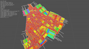
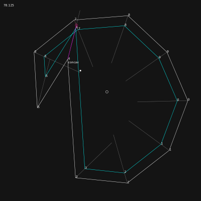
The straight skeleton[6] being used here to generate the borders of the roads and the shapes of the building, it has been clear early in the development that the polygon's segments might react differently to the shrink factor. Each side of a polygon represents a portion of road. The road, depending on its importance, might have a different width. When the shrink is process, this differences of width generate discontinuities in the speed of the segments. The weight of the segment represents this idea, and is used as a multiplier on the shrink factor requested.
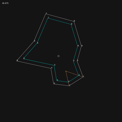
This image represents the difference of weight on different segment of the polygon. On the right, higher weights implies a bigger translation of the segment.
Events have to take the weight into account. A part of the work has been done on the split events, but the results are still buggy, see blue polygon on second and third screenshots.
Export/import
CSV and SVG exports are available (to be documented).
References
- ↑ Finding the closest road on the right at a crossroad, originally posted in polymorph.cool
- ↑ tmpearce on stackoverflow
- ↑ Dr. Martin von Gagern on stackoverflow
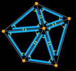
- ↑ 4.0 4.1 The half-edge data structure is called that because instead of storing the edges of the mesh, we store half-edges. As the name implies, a half-edge is a half of an edge and is constructed by splitting an edge down its length. We'll call the two half-edges that make up an edge a pair. Half-edges are directed and the two edges of a pair have opposite directions. Source: flipcode.com. Doubly connected edge list, also known as half-edge data structure. Source:wikipedia
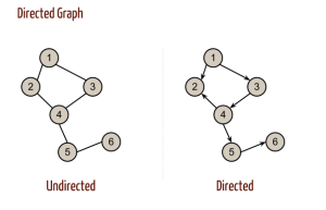
- ↑ In mathematics, and more specifically in graph theory, a directed graph (or digraph) is a graph that is a set of vertices connected by edges, where the edges have a direction associated with them. Source:Directed graph
- ↑ 6.0 6.1 Straight Skeleton on wikipedia
- ↑ 7.0 7.1 7.2 Computing Straight Skeletons by Means of Kinetic Triangulations, Peter Palfrader master’s thesis, Department of Computer Sciences, University of Salzburg, 2013 - pdf
- ↑ See page notes about math, chapter Segments intersection
- ↑ The Mamas & the Papas was an American folk rock vocal group that recorded and performed from 1965 to 1968, reuniting briefly in 1971. wikipedia
- ↑ Joe Cocker, With A Little Help Of My Friends, 1969, https://en.wikipedia.org/wiki/With_a_Little_Help_from_My_Friends
- ↑ Processing is a flexible software sketchbook and a language for learning how to code within the context of the visual arts. - https://processing.org/
- ↑ The train problem is a basic math exercice, in wich distance and speed of the trains are involved - mathscore.com, mathforum.org
- ↑ Multigon is a concept used in code to describe a group of polygons. The correct form would be multipolygon, but have been compressed for better code and oral fluidity.
Resources
- Doubly connected edge list, also known as half-edge data structure - wikipedia
- Segments' intersection & Segments' crossing in Notes:Math
- Paths: Stroking and Offsetting http://tavmjong.free.fr/blog/?p=1257
Solving via the 3rd dimension:
